Table of Contents
Advertisement
Quick Links
Advertisement
Table of Contents

Subscribe to Our Youtube Channel
Related Manuals for Dnake 280M-S8


Summary of Contents for Dnake 280M-S8
- Page 2 REMARK Please follow the user manual for correct installation and testing. If there is any doubt please call our tech-supporting and customer center. Our company applies ourselves to reformation and innovation of our products. No extra notice for any change. The illustration shown here is only for reference.
-
Page 3: Table Of Contents
CATALOG Product Features .............1 Technical Parameters ..........1 Package Contents...........2 Pictures..............2 Operations ...............3 1. Security ..............4 2. Smart ..............9 3. Intercom .............12 4. Message ..............14 5. Setup ..............15 Web Settings............18 System Configuration..........20 System Diagram ............21 Installation .............23 Troubleshooting............24 Safety Instructions..........25... -
Page 4: Product Features
PRODUCT FEATURES 1. Building intercom application: Talkback: Support video call, monitoring, unlocking and checking of call records. Security: Support 8 alarm zones with three states, zone and scene setup. Smart: Support smart home extension by RS485 communication. 2. Operating system: Linux. TECHNICAL PARAMETERS Voltage: DC 12V Rated power: 9W... -
Page 5: Package Contents
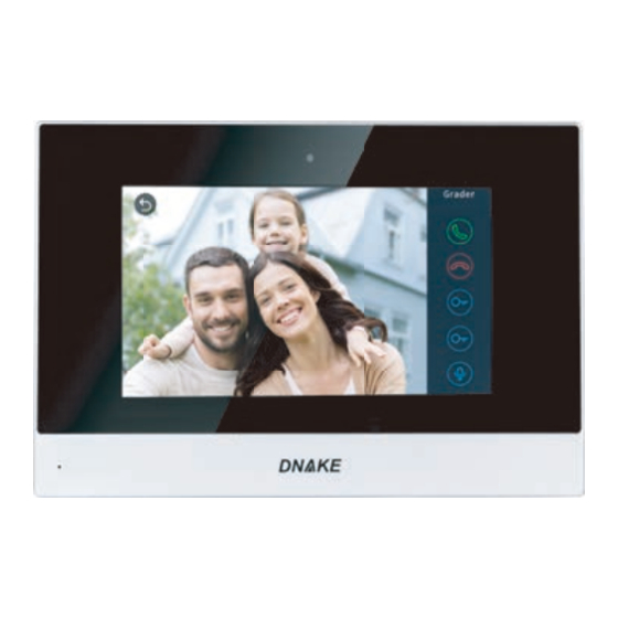
PACKAGE CONTENTS MODEL: 280M-S8 Indoor Monitor Quick Start Guide Screw PICTURES 7'' capacitive touch screen Speaker Microphone... -
Page 6: Operations
OPERATIONS Main menu: Security, Smart, Intercom, Message and Setup. Status bar: Network connection and security precautions. Shortcut key: Do Not Disturb, Message, Records. Instructions of status bar and shortcut key: 1. DND :Click icon, the system will enter DND or undo DND. You can use Do Not Disturb service when you don't want to be disturbed by calls(The valid time is 8 hours). -
Page 7: Security
1.Security Clicking “Security” icon on the main interface, the system will enter the following interface: 1.1 ON/OFF Clicking “ON/OFF” icon, the system will enter the following interface: 1.1.1 ON Click “Out” “Home”, or “Sleep” icon to activate the alarm sensors. The corresponding icon on the main interface will be lit up with a beep and it will stay lit. - Page 8 1.2 Camera Clicking “Camera” icon, the system will enter into the following interface: Click icon or icon button to select the camera you want, and then click to monitor the IP camera. If you want to cancel monitoring, click to stop it. 1.2.1 IP Camera Setting Login the webpage of indoor monitor by username: user, password:1234, and then you can access the following webpage:...
- Page 9 Fill in with the RTSP format: rtsp:// user: password@ Camera IP. IP is the IP address of your IP Camera. Then you can monitor IP Camera in Security menu on your indoor monitor: Clicking “Camera” icon, the system will enter into the following interface: Click icon or icon button to select IP Camera to monitor, and then...
- Page 10 Type Mode Delay Sensor 24 Hour Smoke Smoke 24 Hour Smoke 24 Hour 24 Hour Smoke Smoke 24 Hour Smoke 24 Hour 24 Hour Smoke Smoke 24 Hour 1.3.1 Alarm Type Clicking input box of type, a dialog box will pop up as below. On this interface, you can set alarm type as: Normal, Emergency or 24H.
- Page 11 When alarm sensor is triggered, the indoor monitor will make a loud alarm sound, and the system will enter into the following interface as well as send alarm message to master station(if master station is installed in your system): You can see the No. and sensor type in red color shown at the top of interface.
-
Page 12: Smart
refers to Alarm ON, and refers to Alarm OFF. To set the sensor of alarm stations, you can click the corresponding station with icon. Click "Activation time" to choose the corresponding time. The options of activation time include NONE, 30s, 40s, 60s, 100s and 300s. 1.5 Setup Clicking “Setup”... - Page 13 2.1 Scene Clicking “Scene” icon, the system will enter into the following interface: Scene mode includes: Home, Out , Dinner, Party and Sleep. 2.2 Light Clicking “Light” icon, the system will enter into the following interface: Set the light of corresponding room, such as Master, Sub, Living and Dining Rooms (see the room setting for details).
- Page 14 2.4 Curtain Clicking “Curtain” icon, the system will enter into the following interface: By clicking “Close” icon, the curtain will be closed; by clicking “Open” icon, the curtain will be open; by clicking “Pause” icon, the curtain will be paused. 2.5 Elevator Clicking “Elevator”...
-
Page 15: Intercom
3.Intercom Clicking “Intercom” icon on the main interface, the system will enter into the following interface: 3.1 Call Out Clicking “Call Out” icon, the system will enter the following interface: 3.1.1 Call unit resident Input 1-3 digit building No.+ “Building” + 2-digit Unit No. + “Unit” +4-digit room No., then click icon to call. - Page 16 When answering the call, the system will enter into call status: Click icon to communicate with door station A; click icon to end the call; click icon to unlock the door. 3.1.2 Call management center Clicking “Center” icon to call management center (namely master station), the system will call management center 1 to 5 sequentially.
-
Page 17: Message
Click “Door1” icon to switch the type of door station, then click icon to select the area you want to monitor, and click icon to monitor the door station or secondary door station. Click icon to stop monitoring. Click icon to unlock the door. Remark: The system’s default monitoring time is 25s. -
Page 18: Setup
Note: only by installing the management software on PC which is usually located at guard center, can indoor monitor receive the message sent by Click icon to page up; click icon to page down; click icon to delete the record. 5. - Page 19 5.3 Network Click “Network” icon, then input 1-16 digits password (the default password is 123456 ) to enter into the following interface: IP: the system will automatically display IP address of the indoor monitor. IP address is unique. The default Mask address is 255.255.255.0. Normally, it is unnecessary to modify. If you would like to modify it, a keypad will pop up when clicking the setting box twice.
- Page 20 You can set the new system password with 1-16 digits (the default password is 123456). System password is used for system settings. 5.5 Version Click “Version” icon to enter into the following interface: You can look over the relevant information.
-
Page 21: Web Settings
WEB SETTINGS Please refer to 5.3 to view IP address. Connect the indoor monitor and computer by network switch. Input the indoor monitor’s IP address in the browser, then input user name and password (the default user name is “admin”, the password is “123456" to enter into the web setting interface). - Page 22 Please refer to 5.2 for room settings. Click “Submit” icon to save the settings. 3. VOIP Click “VOIP” icon to enter into the following interface: The settings are the same with the ones of indoor monitor. To connect with SIP phone, check “Enable” and input the number registered in SIP server.
-
Page 23: System Configuration
SYSTEM CONFIGURATION System Configuration CAT-5e+RVV2 CAT-5e+RVV2 Terminal *1.0 CAT-5e Audio extension (optional) CAT-5e Audio extension (optional) Terminal *1.0 Power 220V Power 220V Audio extension (optional) Audio extension (optional) Network Switch Network Switch RVV2*0.5 RVV2*0.5 Terminal Terminal 220V 220V Power Power CAT-5e CAT-5e Audio extension (optional) -
Page 24: System Diagram
SYSTEM DIAGRAM Network(POE) Power RS485 Interface Siren/Alarm 1. Power Power input interface connect with 12V power adapter. +12V +12V DC 12V Power Interface 2. Network Connect with outdoor panel, indoor monitor or other network equipment by network switch. When indoor monitor has PoE function, the interface can supply power by connecting with PoE network switch. - Page 25 3. RS485 Interface Connect with RS485 interface device; RS485 interface can output 12V/100mA power supply. If RS485 equipment to be connected doesn’t require the power supply, no need to connect +12V. +12V +12V RS485 Interface RS485 Equipment 4. Alarm interface Interface of alarm zones connects with normally-open or normally-closed switch.
-
Page 26: Installation
INSTALLATION Built-in box Bracket Screws Size: 221.4x151.4x16.5mm Installation Instructions: [Suggestion]: During the installation, the camera should be 1450〜1550mm above the Wall ground. The camera tether for photographing human face should be the top priority. 400~500mm... -
Page 27: Troubleshooting
TROUBLESHOOTING The indoor monitor cannot start up or power off automatically. Check whether it has power-failure, and power it on again. The indoor monitor display screen is too dim. Check whether the brightness and contrast settings of screen are correct. No sound during the communication. -
Page 28: Safety Instructions
SAFETY INSTRUCTIONS In order to protect you and others from harm or your device from damage, please read the following information before using the device. Do not install the device in the following places: Do not install the device in high-temperature and moist environment or the area close to magnetic field, such as the electric generator, transformer or magnet. - Page 29 V1. 0...
Need help?
Do you have a question about the 280M-S8 and is the answer not in the manual?
Questions and answers