
Related Manuals for AIC GB207A-CT


Summary of Contents for AIC GB207A-CT
- Page 1 GB207A-CT General Purpose S erver Barebone User’s Manual Document Number: MAN-00104-A ...
-
Page 2: Table Of Contents
Contents Contents ............................1 Safety Information ........................3 About This User’s Manual ....................4 Chapter 1: Product Introduction ................... 1.1 General Information ..........................5 1.2 System Specifications ..........................6 1.3 Front View of GB207A‐CT ........................8 1.4 Rear View of GB207A‐CT .........................8 1.5 Top View of GB207A‐CT...........................9 Chapter 2 : Hardware Setup .................. - Page 3 6.5 Updating BMC Configuration.........................45 Chapter 7 : Technical Support ..................46 Copyright © 2011 AIC Inc. All Rights Reserved. This document contains proprietary information about AIC products and is not to be disclosed or used except in accordance with applicable agreements. ...
-
Page 4: Safety Information
Safety Information When installing, operating, or performing maintenance on this equipme nt, basic safety precautions, as listed b elow, should always be followed to reduce the risk of fire, electric shock, and personal injuries. Read and understand all instructions. ... -
Page 5: About This User's Manual
About This User’s Manual This document provides a detailed description of the GB207A-CT including: The General Features of the Product Hardware Setup Motherboard Settings Backplane Settings BIOS Configuration and Settings BMC Configuration and Settings ... -
Page 6: Chapter 1: Product Introduction
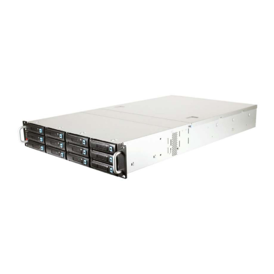
GB207A-CT, a 2U 12bay General Purpose Barebone, supports Dual-Core /Quad-Core/6- /Quad-Core/6- Core processors. GB207A-CT has 12 x 3.5” (Front) + 2 x 2.5” (Rear Core processors. GB207A-CT has 12 x 3.5” (Front) + 2 x 2.5” (Rear OS) size HDD bays w/o OS) size HDD bays w/o expander to maximize I/O bandwidth. -
Page 7: System Specifications
1.2 System Specifications Dimensions (w ith chassis ears/pro trusions) mm : 482.6 x 736.6 x 88.8 W x D x H inches : 19 x 29 x 3.5 Motherboard Motherbo Castor (PSG-M-CTDP036D-110) Processor Dual L GA1366 sockets to support Dual-core/Quad-core/6-Core Intel® Xeon Processor Support processors 5500/5600 series (Nehalem/Westmere) System Bus... - Page 8 System BIOS • AMI BIOS BIOS Type • SPI (Seri al Peripheral In terface) FLASH Inte rface • A CPI 1.0/2.0/3.0 • IPMI KCS interface • PXE 2.0 • SMBIOS 2. BIOS Features • WOL • Serial console redirection •...
-
Page 9: Front View Of Gb207A-Ct
LED Color Behavior Soli d: System On Power LED Green Power ON/OFF Push for Power On or Off Off: System Off Light: Link AN LED Green System Reset Push for System Reset Blink: Activity HDD LED Green Blink: A ctivity 1.4 Rear View of GB207A-CT 2 x USB ports 4 x RJ45 ports DB‐9 serial port High efficiency 650W 1+1 redundant power supplies 80+ VGA port ... -
Page 10: Top View Of Gb207A-Ct
1.5 Top View of GB207A-CT The barebone server includes the basic components shown below. Hot‐swap HDD Trays SAS/SATA Backplane System Fans Castor Motherbo ard Expansion Slots Power Supply Hot‐swap HDD Trays Slim CD‐ROM Rear I/O ... -
Page 11: Chapter 2. Hardware Setup
Chapter 2. Hardware Setup This section demonstrates maintenance procedures in replacing a defective part once e part once the GB207A-CT appliance is installed and is operational. the GB207A-CT appliance is installed and is operational. .1 Chassis Cover .1 Chassis Cover 2.1. -
Page 12: Central Processing Unit (Cpu)
2.2 Central Processing Unit (CPU) Caution : When unpacking a processor, hold the processor nly by its dges to avoid touching the contacts. 2.2.1 Installing the CPU 1. Press the load lever to release the load plate. Load lever ... - Page 13 4. Align the processor cutouts against the socket notches. Cutouts Caution: The pins of the processor socket are vulnerable and easily susceptible to damage if fingers or any foreign objects are pressed against them. Please keep the socket protective cover on when processor is not installed.
-
Page 14: Installing The Cpu Heatsink
2.2.2 Installing the CPU Heatsink Note: Apply thermal paste to the bottom of heatsink and spread in To install the CPU heatsink: an even thin layer before installing the heatsink. 1. Place the heatsink on top of the CPU, ensuring that the four fasteners match the holes on the motherboard. -
Page 15: System Memory
2.3 System Memory This server board supports up to tw elve DDR3 800/1066/1333 Registered ECC SDRAM (recommended) / Unbuffered ECC SDRAM. 1. Populate DIMMs in the following DIMM MM arrang ment Numbers 2 DIMMs CPU0 DIMM 0 CPU1 DIMM 0 4 DIM CPU0 DIMM CPU0 DIMM 0... - Page 16 10 DIMMs CPU0 DIMM 0 CPU0 DIMM 0 CPU0 DIMM 0 DIMM 1 DIMM 1 CPU1 DIMM 0 CPU1 DIMM 0 CPU1 DIMM 0 DIMM DIMM 1 CPU0 DIMM 0 CPU0 DIMM 0 CPU0 DIMM 0 12 DIMMs DIMM 1 DIMM 1 DIMM 1 CPU1 DIMM 0...
-
Page 17: Drive Bays
2.4 Drive Bays 2.4.1 Installing or Replacing 3.5” Hot-swap SAS/SATA HDD 1. Release a drive tray by pressi ng the unlock button and pinching slightly the lock lever and pulling out the drive tray. 2. Firmly hold the tray lever and pull the drive out of the bay. ... -
Page 18: Installing Or Replacing 2.5" Hot-Swap Sas/Sata Hdd
2.4.2 Installing or Replacing 2.5” Hot-swap SAS/SATA HDD 1. Release a drive tray by pressin g the unlock button and pinching slightly the lock lever and pulling out the drive tray. Firmly hold the tray lever and pull the drive out of the bay. ... -
Page 19: Slim Cd-Rom/Dvd-Rom
2.5 Slim CD-ROM/DVD-ROM 2.5.1 Installing Slim CD-ROM/DVD-ROM 1. Release the four screws to remove the slim CD-ROM/DVD-ROM bracket. 2. Release the two screws to separate the bracket holder and dummy cover. 3. Place the sl im CD -ROM/DVD-ROM on the tray holder and then secure it with 8 screws fro m bot h sides. -
Page 20: Riser Card Setting
4. Place the slim CD-ROM/DVD-ROM into the tray with four screws. 2.6 Riser Card Setting 1. RISER CARD PN (PSG CODE) DESCRIPTION PSG-RC-CT2U-40-110(PE2U05) 2U Gold finger 2 PCIe Gen2 X16 to 1 PCIe X16 + 1 PCIe X8 + 1 PCIe X8 (X4 lane) Riser or 1 PCIe X16 (X8 lane) + 2 PCIe X8 + 1 PCIe X8 (X4 lane) Riser for Castor RISER CARD DIAGRAM... -
Page 21: Expansion Slot
On Motherboard O FF O FF 2. RISER CARD PN (PSG CODE) DESCRIPTION PSG-RC-CTOB-10-110(PE1U09) 1U on-board PCIe Gen2 X8 to 1 PCIe X8 (low- profile) Riser for Castor RISER CARD DIAGRAM Slot Bandwidth X8 2.7 Expansion Slot 2.7.1 Removing the MB tray 1. -
Page 22: Removing The Mb Tray
2. Remove the screws and thumbscrew on the panel. Re move all the connection cables. Then firmly hold the tray lever and pull the MB tray out of the barebone. 2.7.2 Install an External Expansion Card to the Riser Card 1. - Page 23 3. Install the full-height, half-length expansion card into the p roper slot and connect the expansion card to the ri ser card. 4. Install the half-height, half-length expansion card into the proper slot and connect the expansion card to the riser card. 5.
-
Page 24: Installing An External Expansion Card To The Riser Card (Low-Profile)
2.7.3 Installing an External Expansion Card to the Riser Card (Low-profile) 1. Remove the four screws to release the slim CD-Rom bracket. 2. Remove the three screws, and twist out the metal plate to insert expansion card I/O parts. 3. -
Page 25: System Fans
4. Secure the bracket back with screws to fix the expansion card. .8 System Fans 2.8.1 Removing or Replacing the System Fans 1. Remove the fan module by lifting it from the server chassis and pulling it out. 2.9 Power Supply 2.9.1 Removing or Replacing the Power Supply Module 1. -
Page 26: Motherboard Layout
Motherboard Settings This sec This sec tion describes the jumper settings of AIC’s Castor PSG-M-CTD036D-110 tion describes the jumper settings of AIC’s Castor PSG-M-CTD036D-110 motherboard. We will show the motherboard layout and important jumper settings of motherboard. We will show the motherboard layout and important jumper settings of the system. - Page 27 3.2.1 Jumpers DISABLE VGA DISAB ENABLE ISABLE AST ARM ENABLE RESET AST ARM RESET NORMAL NORMAL CLEAR CMOS CLEAR OPEN INVALID PCIe Strapping Configuration ...
- Page 28 3.2.2 Internal Connectors 1.Tx BMC DEBUG 2.Rx 9.NC 10.GND 7.RI# 8.DTR# UART/COM2 5.CTS# 6.TXD 3.RTS# 4.RXD 1.DSR 2.DCD# 15.GND 16.CLK 13.GND 14.GND 11.V_SYNC 12.DVO_5V 9.NC 10.H_SYNC VGA HEADER 7.GND 8.BLUE 5.DATA 6.GND 3.GREEN 4.NC 1.GND 2.RED 1.KB_DATA 2.+5V 3.KB_CLK KB/MS 4.MS_CLK 5.MS_DATA...
- Page 29 3.2.3Internal Connectors (continue) 5.BMC _GPIOE6 6.BMC_GPIOB2 BMC GPIO 4.BMC_G PIOB7 3.BMC_GPIOE7 1.GND 2.BMC_GPIOH3 2.3.3V 1.GND 4.GPIOF33 3.GPIOF0 6.GPIOF32 5.GPIOF1 8.GPIOF22 7.GPIOF6 10.GPIOF37 9.GPIOF17 1.5V_AUX 2.I2C_CLK PSU I2C 3.I2C_ DATA 4.GND 1.I2C_DATA 2.GND IPMB I2C 3.I2C_CLK 4.NC 1.USB5V 2.USB5V 3.USBD- .USBD- 5.USBD+ 6.USBD+...
- Page 30 3.2.4 Internal LEDs LED ON =LAN LINK LED BLIN K=ACTIVE 1.GbE1 LED# 2.GbE1 LED+ LAN LED 3.GbE2 LED# .GbE2 LED+ 5.GbE3 LED# GbE3 LED+ 7.GbE4 LED# 8.GbE4 LED+ 9.NC 10.3.3V 1.GND 2.CLK_33M 3.NC 4.ICH_LPC_LFRAME# 5.NC 6.SIO_PLTRST# DEBUG PORT 7.ICH_LPC 8.ICH_LPC_LAD3 9.ICH_LPC_LA 10.+3.3V...
-
Page 31: Chapter 4 : Backplane Settings
Chapter Backplane Settings 4.1 SAS/SATA 3G/6G 4-in-1 BP with SGPIO support 1. Front View of Backp lane HDD1 HDD2 HDD3 HDD4 2. Rear View of Backplane J1 CN5 JP2 JP1 CN6 J2 CN7 CN6,CN7: 4Pin Power connector for +12V and +5V Power input JP1: External HDD Accessing LED Input ( Active Low ) in no Description... - Page 32 J2: Function S elect Status Description Open Disable External Access LED input ( JP1 ) Close Enable External Access LED input ( JP1 ) Open Access LED from HDD Pin P11 Close Access LED from SGPIO Open SGPIO Bit2 is HDD Fail, Bit3 is HDD ID Close SGPIO Bit2 is HDD ID, Bit3 is HDD Fail Open...
-
Page 33: Sas/Sata 6G 2-In-1 Bp
4.2 SAS/SATA 6G 2-in-1 BP 1. Front View of Backplane J2: SAS HDD Receptacle Connector- HDD1 D12: HDD1 Preset/Activity LED [blue] D11: HDD1 Fault LED [red] J6: SAS HDD Receptacle Connec tor- HDD2 D13: HDD2 Preset/Activity LED [blue] D14: HDD2 Fault LED [r J2: SAS HDD Receptacle Connector- HDD1 2. - Page 34 J3: HDD1 LED pin he ader Description HDD1 Fault LED(-) HDD1 Fault LED input – Low active LED(+) HDD1 Activity LED(-) HDD1 Activity LED output – Low active J7: HDD2 LED pin header Description HDD2 Fault LED(-) 2 HDD2 Fault LED input – Low active LED(+) HDD2 Activity LED(-) HDD2 Activity LED output –...
-
Page 35: Bios Setting
Chapter ter 5. BIOS Configuration and Settings BIOS Configuration and Settings Caution: When Quiet Boot IS enabled, OEM LOGO WILL BE displayed INST EAD OF POST MESSAGES. 5.1 BIOS Setting 5.1 BIOS Setting 1. Press DEL to run the setup procedure. 1. - Page 36 3. Identify the BIOS Version 4. Load Optimal Default setting 5. Save the setting and exit the BIOS setup utility. ...
-
Page 37: Updating Bios
BIOS update utility with command line interface that works in DOS environment. 2. The latest BIOS version is availab le from the FAE or AIC website. 3. Enter “flash” at the DOS com mand line. 4. Reboot the system after the update. -
Page 38: Chapter 6 : Bmc Configuration And Settings
Chapter BMC Configuration and Settings Insert BMC IP LAN into the BMC LAN port. There are two methods to setup BMC IP: BMC management port 6.1 Method 1 (Use the BIOS setup) 1. BIOS SETUP -> Advance -> IPMI configuration -> Set LAN configuration ... - Page 39 Input IP address. Set IP static. Note: type “1” for selecting static IP mode or type “2” for selecting DHCP mode. Input subnet mask address. ...
-
Page 40: Method 2 (Use A Dos Tool - Syscheck)
6.2 Method 2 (Use a Dos tool - Syscheck) 1. Type : sc –lanset. 2. Modify IP setting. Note: type 1 for selecting static IP mode or type 2 for selecting DHCP mode. ... - Page 41 3. Input IP address. 4. Input submask address. Below IP address is an example using a default IP setting. User is allowed to change the IP address for realistic use. 5. Finish BMC IP configuration. Note: Type sc.exe –langet command to obtain BMC IP and MAC address. ...
-
Page 42: Connect To Bmc
6.3 Connect to BMC Note: This feature works with JAVA 6 runtime installed console environment. Below IP address is an example using default IP setting. User is allowed to change the IP address for realistic use. 1. Open the browser then type default BMC IP address: 192.168.22.22 2. - Page 43 Note: Users who login with the root user name and password will have full administrative power. The root password can be changed after login. 3. Information of ASTER firmware. 4. Server Health - Sensor Readings: 5. Configuration Please refer to AIC BMC User Guide for more information on AIC BMC. ...
- Page 44 Mouse Mode setting: For Windows OS environment, set mode to absolute. For Linux OS environment, set mode to relative. Remote Control: Environme l setting: ...
-
Page 45: Updatin G Bmc Firmware
A:>cd AQUAN120 A:\ AQUAN120>a.bat s is just an example. The latest BMC firmware version is available from the FAE or AIC website. After update BMC firmware, please power off and then pow er on system. Notes: 1. DO NOT USE EMM386 IN DOS ENVIRONMENT WHEN UPDATING FIRMWARE OR YOU WILL GET A FAIL. -
Page 46: Updating Bmc Configuration
RE THAT HAS BEEN TESTED AND APPROVED FOR EACH SPECIFIC PRODUCT . PLEASE MAKE SURE FIRMWARE AND CONFIGURATION VERSIONS ARE COR RECT BEFORE UPDATING. CONSULT THE AIC WEB SITE ( http://www.aicipc.c ) FOR THE CORRECT COMBINATION OF FIRMW ARE AND CONFIGURATION VERSIONS FOR YOUR SYSTEM. -
Page 47: Chapter 7 : Technical Support
886.3.313.8386 Fax: +886.3.313 .8377 Email Technica l Support: support@aicipc.com JAPAN Tel: +81. 43.202.8380 Fax: +81.43.20 2.8381 Email Technical Support: support@aic ipc.com CHINA Tel: +021.54961 421, +021.54961422 Fax: Extension: 6 Email Technical Support: support@aicipc.com AMERICA - W est coast ... - Page 48 Note ...
Need help?
Do you have a question about the GB207A-CT and is the answer not in the manual?
Questions and answers