Lincoln FlowMaster B Series Manual
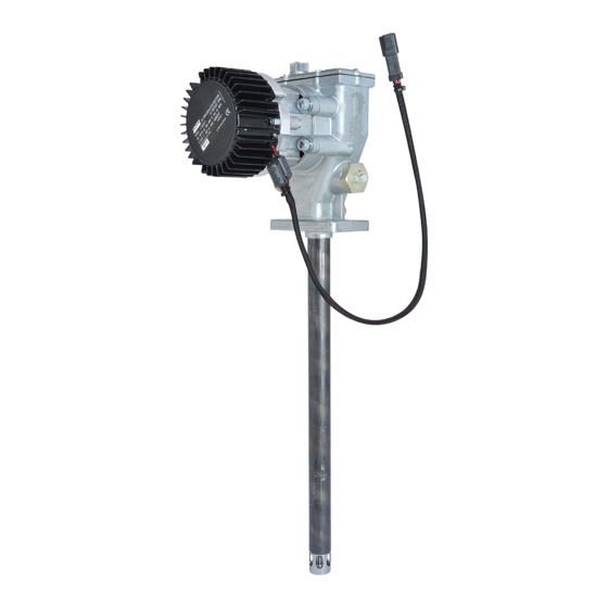
Rotary driven hydraulic pump 90 lb / 60 lb
Hide thumbs
Also See for FlowMaster B Series:
- Manual (62 pages) ,
- Installation and maintenance manual (28 pages) ,
- Manual (40 pages)
Table of Contents
Advertisement
Quick Links
FlowMaster
FlowMaster
Models/Modelle: 85676 (90#), 85678 (60#)
U.S. Patent No. 6,102,676
U.S. Patent 6,102,676
Foreign Patent Pending
Ausländisches angemeldet
This pump conforms to the European Directive for Product Safety
Diese Pumpe entspricht der europäischen Vorschrift für Produktsicherheit
MAY - 2008
Rotary Driven Hydraulic Pump
®
Pumpe mit Hydraulik-Umlaufantrieb
®
Series "B"
Form 403750
- C8
Section
Page
- 319A
Advertisement
Table of Contents

Subscribe to Our Youtube Channel
Related Manuals for Lincoln FlowMaster B Series


Summary of Contents for Lincoln FlowMaster B Series
- Page 1 FlowMaster Rotary Driven Hydraulic Pump ® FlowMaster Pumpe mit Hydraulik-Umlaufantrieb ® Models/Modelle: 85676 (90#), 85678 (60#) Series “B” U.S. Patent No. 6,102,676 U.S. Patent 6,102,676 Foreign Patent Pending Ausländisches angemeldet This pump conforms to the European Directive for Product Safety Diese Pumpe entspricht der europäischen Vorschrift für Produktsicherheit - 319A - C8...
-
Page 2: Table Of Contents
General Description Safety Instructions The Lincoln Industrial rotary Hydraulic Pump is a fully hydraulically This equipment generates very high grease pressure. Ex- operated grease pump. Grease output is proportional to the hy-... -
Page 3: Appropriate Use
FlowMaster™ Rotary Driven Hydraulic Pump Appropriate Use in during the previous stroke is transferred through the outlet check and discharged to the outlet port. Typical output of the dispense lubricants using hydraulic power. pump is shown on page 4. exceeded. result in loss of claims for warranty and liability. - Page 4 FlowMaster™ Rotary Driven Hydraulic Pump 80°F (27º C) 20°F (-7º C) 0°F (-18º C) -20°F (-29º C) A - Pump Outlet Plug B - Hydraulic Supply Line C - Hydraulic Return to Tank line (3/4” ID min.) D - Supply Line Shut-off Valve E - 24 VDC from Controller F - Return Line Shut-off Valve (3/4”...
-
Page 5: Installing The Pump
Maintenance and Repair Relieve pressure from the pump and supply lines before servicing or repairing the pump, to reduce the risk of an injury Always use Lincoln Industrial parts for service and repair. Illustration 4 * Included in Spacer Kit 272013... - Page 6 FlowMaster™ Rotary Driven Hydraulic Pump © Fill with SAE 10W30 Motor Oil for all pumps. MODEL DIM “A” in (mm) DIM “B” in (mm) 85676 27.5 (699) 38.56 (980) 85678 19.00 (483) 30.06 (764) Page Number - 6 Form 403750...
-
Page 7: Troubleshooting
FlowMaster™ Rotary Driven Hydraulic Pump Troubleshooting Condition Possible Cause Corrective Action Pump does not run. No pressure on gauge (72): - Closed Supply line shut off valve. Open shut-off valve. - No power to solenoid valve (73). Correct electrical fault. - Faulty Solenoid (74). - Page 8 Sicherheitshinweisen und dieser Betriebsanleitung genau vertraut gemacht haben. Fluss- und Druckregelungventilen der Korrekturmöglichkeit Allgemeine Beschreibung Die FlowMaster Pumpe mit hydraulischem Umlaufantrieb von Lincoln Industrial ist eine völlig hydraulisch betriebene Fettpumpe. Die dung in Zentralschmiersystemen, wie Einleitungs-, Progressiv- und Zweileitungssystem, ausgelegt.
- Page 9 FlowMaster Pumpe mit Hydraulik-Umlaufantrieb Bestimmungsgemäße Verwendung Alle Pumpenmodelle sind für hydraulischen Antrieb ausgelegt und Hydraulikmotor (Teil 42) Hydrauliköl Tank (Teil 39) Magnetventil (Teile 34* & 35) Manometer (Teil 32) Entlastungsventil Modell 85676 nur (Teil 38) 24V DC Anschlüsse ren Kabelkopf Technische Daten Magnetventil Hydraulik-Eingangsdruck,...
- Page 10 FlowMaster Pumpe mit Hydraulik-Umlaufantrieb Schmierstoff-Förderleistung vs. Hydraulik-Volumenstrom 30º C 0º C -10º C -30º C Hydraulik-Volumenstrom (l/min) Schmierstoff-Förderleistung vs. Hydraulik-Volumenstrom 80º F 20º F 0º F B - Hydraulik-Druckleitung mindestens 3/4“ (19 mm) I.D. D - Absperrventil (Hydr. Druckleitung) -20º F E - 24V DC Steuerleitung 3/4“...
- Page 11 FlowMaster Pumpe mit Hydraulik-Umlaufantrieb Betrieb Installation der Pumpe Alle Pumpen sind werkseitig auf 300 PSIG (20,7 bar) Hydraulik-Ar- Die hier beschriebene typische Installation wird nur beitsdruck und 2 gpm (7,6 l/min) Volumenstrom eingestellt. Versuchen als Richtlinie für die Auswahl und Installation der Sie nicht, diese Einstellungen zu ändern.
- Page 12 FlowMaster Pumpe mit Hydraulik-Umlaufantrieb Modell Maß “A” Zoll (mm) Maß “B” Zoll (mm) 85676 27.50 (699) 38.56 (980) 85678 19.00 (483) 60.06 (764) Seite - 12 Formular 403750...
- Page 13 FlowMaster Pumpe mit Hydraulik-Umlaufantrieb FEHLERSUCHE Störung Mögliche Ursache Behebung Pumpe läuft nicht - Absperrventil der Zufuhrleitung geschlossen. Absperrventil öffnen. - Am Magnetventil (74) liegt keine Spannung an. Elektrischen Fehler beheben. - Magnetventil-Spule (74) defekt. Hydraulikversorgung auf richtigen Druck beseitigen. Ventil um eine ¾ Drehung öffnen. - Pumpe wurde durch Aufbau von Gegendruck Entlastungsventil im System prüfen in der Schmierstoff-Förderleitung angehalten.
- Page 14 FLOWMASTER HYDRAULIC PUMP Repair Instruction Page Number - 14 Form 403750...
- Page 15 FLOWMASTER HYDRAULIC PUMP Repair Instruction 34 33 Included in 56a Page Number - 15 Form 403750...
- Page 16 FLOWMASTER HYDRAULIC PUMP Repair Instruction © Indicates change Page Number - 16 Form 403750...
- Page 17 FLOWMASTER HYDRAULIC PUMP Repair Instruction Repair Parts (for all models) Item No. Qty Description All Models Item No. Qty Description All Models Flat Head Screw (1/4 x 1-3/4) 270635 O-Ring Counter Weight 272197 O-Ring Retaining Ring 270609 Backup Washer Crankrod 270665 Hydraulic Motor Kit 274054...
-
Page 18: Repair Parts List
FLOWMASTER HYDRAULIC PUMP Repair Instruction Repair Parts List (Non-common items) Item Qty. Description Model Model 85676 85678 Plunger Link Rod 270648 270614 Reciprocating Tube 270649 270617 Housing Tube 270659 270660 © Indicates change Page Number - 18 Form 403750... -
Page 19: Repair Instructions
FLOWMASTER HYDRAULIC PUMP Repair Instruction TN ANZ BESCHREIBUNG ALLE MODELLE BESCHREIBUNG ALLE MODELLE 270635 Auslass, Stiftmutter 270619 Gegengewicht 272197 O-Ring Haltering 270609 O-Ring Kurbelstange 270665 Haltering 270608 274054 (enthält Dichtung (Teil 69) und 2 O-Ringe (Teil 68)) 270666 Kugellager 270607 Innensechskantschraube (1/2 x 1-1/4) 270658 Auslassstift... - Page 20 FLOWMASTER HYDRAULIC PUMP Repair Instruction Ersatzteilliste (Nicht gemeinsame Teile) Teilno. Anz. Beschreibung Modell 85676 Modell 85678 (90 lb) (60 lb) Kolbenverbindungsstange 270648 270614 Pumpenkolbenrohr 275018 275022 Gehäuserohr 275195© 275194© Page Number - 20 Form 403750...
- Page 21 FLOWMASTER HYDRAULIC PUMP Repair Instruction Repair Kit Selection Chart Converting Series A to Series B Pumps Series A Service page needed for teardown Series B Service page needed for re-assembly Item # Kit # 1 to 8, 24, 25, 27, 32, 36 to 52, 58 to 67 No kit –...
- Page 22 FLOWMASTER HYDRAULIC PUMP Repair Instruction Repair Kit Selection Chart Repair Series B Only Item # Kit # 1 to 8, 24 to 30a, 36 to 52, 56a to 67 Not in kits, order individually if needed 9, 10, 10a, 10b, 10c, 10d, 14, 15, 275186 - Upper Bushing &...
- Page 23 FLOWMASTER HYDRAULIC PUMP Repair Instruction Reparatursatz-Auswahltabelle Teilnummer Reparatursatz Nummer 1 bis 8, 24, 25, 27, 32, 36 bis 52, 58 bis 67 9, 10, 10a, 10b, 10c, 10d, 14, 15 17, 18, 19, 19a, 21 und 26 Für die Teilnummer des Kolbenrohrs siehe Tabelle auf Seite 20, Serie B 28, 29, 30 30a, 30b und 31 Teile 56a, 56b und 57...
- Page 24 FlowMaster™ Rotary Driven Hydraulic Pump Reparatursatz Auswahltabelle Nur Reparatur der B Serie Teilnummer Satz Nummer 1 bis 8, 24 bis 30a, 39 bis 52, 56a bis 67 9, 10, 10a, 10b, 10c, 10d, 14, 15 11, 12, 13a, (Abstandsstück 275376 nicht verwenden) 17, 18, 19, 19a, 21, 26 9, 13b, 14, 15, 17, 18, 21, 25, 26, 30b, 31, 33, 34, 35, 53, 54, 55, Page Number - 24...
- Page 25 FlowMaster™ Rotary Driven Hydraulic Pump Tools Required for Maintenance, Repair and Zur Wartung, Reparatur und Einstellung Adjustment benötigte Werkzeuge. 7/16” open end wrench 7/16” Gabelschlüssel 1-1/2” open end wrench 1-1/2” Gabelschlüssel 3/4 open end wrench 3/4“ Gabelschlüssel 12” cresent wrench 12“...
- Page 26 FLOWMASTER HYDRAULIC PUMP Repair Instruction 4) Remove housing cover (Item 30a) and gasket (Item 31). 1) Remove dip stick (Item 30b). (Reassembly torque: (Reassembly recommendations; replace gasket.) 10 - 15 in. lbs. (1.1 - 1.7 Nm).) 1) entfernen Badstock (Einzelteil 30b). (Wiederversammlung- drehkraft: 1,1 - 1,7 Nm (10 - 15 inch lbs).) Sie Dichtung.) 2) Drain crankcase oil (reassembly recommendations: use...
- Page 27 FLOWMASTER HYDRAULIC PUMP Repair Instruction 7) Remove four manifold mounting screws (Item 71). (Reas- sembly torque: 20 - 25 Ft. Lbs. (27.1 - 33.9 Nm).) 7) entfernen vier vielfältige Befestigungsschrauben (Einzelteil 71). (Wiederversammlungdrehkraft: 27,1 - 33,9 Nm (20 - 25 Ft.
- Page 28 FLOWMASTER HYDRAULIC PUMP Repair Instruction 14) Remove the two outlet pin nuts (Item 32). (Reassme- bly torque: 30 - 35 Ft. Lbs.(40,7 - 47,5 Nm).) (Reassembly recommendations: Use Loctite242 or equivalent on outlet nut threads). 14) entfernen die zwei Anschlußnüsse (Einzelteil 32). (Reas- smebly Drehkraft: 40,7 - 47,5 Nm (30 - 35 Ft.
- Page 29 FLOWMASTER HYDRAULIC PUMP Repair Instruction 16. Remove shovel plug (Item 58) and spacer (Item 56) from housing tube. 16. Entfernen Sie Schaufelstecker (Einzelteil 58) und Eingang Schirm (Einzelteil 56) vom Gehäuseschlauch. 15. Remove spiral retaining ring (item 59) from housing tube. 15 Entfernen Sie Seegerring der Spirale (Einzelteil 59) vom Gehäuseschlauch.
- Page 30 FLOWMASTER HYDRAULIC PUMP Repair Instruction 19. Exploded view of housing tube (Item 56a), spacer (Item 56) and Shovel Plug (Item 58). 17. Push pump element (items 1 through 27) out of housing 28. Explosionsdarstellung des Gehäuseschlauches (Einzelteil tube with plastic rod and hammer. (Reassembly recommenda- 56a), des Eingang Schirmes (Einzelteil 56) und des Schaufel- tion: replace pump element in housing tube with housing tube Steckers (Einzelteil 58).
- Page 31 FLOWMASTER HYDRAULIC PUMP Repair Instruction 22. Remove wrist pin bushing screws (Item 11). (Reassem- 25. Remove wrist pin bushing (Item 12). bly torque: 100-110 in. lbs. (11.3 - 12.4 Nm).) Reassembly 25. Entfernen Sie Handgelenkstift Buchse (Einzelteil 12). recommendations: use Loctite 242 or equivalent on screw threads).
- Page 32 FLOWMASTER HYDRAULIC PUMP Repair Instruction 31. Remove plunger tube (Item 10) and associated parts. 28. Remove wrist pin anchor (Item 13a). (Reassemblly recom- (Reassembly recommendations: replace O-ring (Item 10c) on mendations: replace O-ring seal (Item 13b), be sure threads on bushing (Item 10a).
- Page 33 FLOWMASTER HYDRAULIC PUMP Repair Instruction 34. Pull cup seal (Item 15) out of wrist pin anchor (Item 13a). 36. Hold outlet pin (Item 8) and plunger tube (Item 10) in vise. 34. Ziehen Sie Schale Dichtung (Einzelteil 15) Handgelenkstift 36. Halten Sie Anschlußstift (Einzelteil 8) und Spulenkern- Anker heraus (Einzelteil 13a).
- Page 34 FLOWMASTER HYDRAULIC PUMP Repair Instruction 43. Remove backup washer (Item 10b). 39. Remove O-ring (Item 9). 43. Entfernen Sie Aushilfsunterlegscheibe (Einzelteil 10b). 39. Entfernen Sie O-Ring (Einzelteil 9). 40. View of O-ring (Item 9) removed. 40. Ansicht des O-Ringes (Einzelteil 9) entfernte. 44.
- Page 35 FLOWMASTER HYDRAULIC PUMP Repair Instruction 48. Remove lower plunger and bushing assembly (Item 19) 46. Check seat housing assembly (Item 27) and associated from reciprocating tube (Item 20). (Reassembly recommenda- parts removed. (Reassembly recommendations: replace O-ring tions: replace O-ring seal (Item 26.) Remove lower cup (Item seal (Item 26).
- Page 36 FLOWMASTER HYDRAULIC PUMP Repair Instruction 50. With the tool in place, insert the 9/64” drill bit shank through 53. Clamp crank rod/eccentric assembly (Items 1-7) in vise. 53. Reizbare rod/eccentric Klemmplatte (Einzelteile 1-7) im the tool and into the plunger outlet hole. Kolben.
- Page 37 FLOWMASTER HYDRAULIC PUMP Repair Instruction 58. Place assembly on 2” schedule 40 pipe. 58. Bitte Versammlung auf Rohr des 2”Zeitplanes 40. ance weights (Item 2). 59. Drive crank eccentric (Item 6) out of ball bearing (Item 7). fernen Sie Ausgleichsdämpfergewichte (Einzelteil 2). 59.
- Page 38 FLOWMASTER HYDRAULIC PUMP Repair Instruction 63. Reassembly recommendations: To install the O-ring (Item 61. Remove O-Ring seal (Item 33) from outlet nut (Item 32). 34) and backupwasher (Item35) most easily, install the backup 61. Entfernen Sie O-Ring Dichtung (Einzelteil 33) von der Anschlußnuß...
- Page 39 FLOWMASTER HYDRAULIC PUMP Repair Instruction Recommended setting range Emptohler Einstellungs beseich Page Number - 39 Form 403750...
- Page 40 FLOWMASTER HYDRAULIC PUMP Repair Instruction Americas: Europe /Africa/Middle East © Copyright Lincoln Industrial 51 Changi Business Park One Lincoln Way Lincoln GmbH Corp. 2008 Central 2 St. Louis, MO 63120-1578 Printed in USA #09-06 The Signature 69190 Walldorf - Germany Singapore 486066 Phone +1.314.679.4200...
Need help?
Do you have a question about the FlowMaster B Series and is the answer not in the manual?
Questions and answers