
Related Manuals for Cornelius PRISM


Summary of Contents for Cornelius PRISM
- Page 1 PRISM Owner’s Manual Release Date: September 21, 2018 Publication Number: 548000037 Revision Date: April 13, 2022 Revision: F Visit the Cornelius web site at www.cornelius.com for all your Literature needs.
- Page 3 This Product is warranted only as provided in Cornelius’ Commercial Warranty applicable to this Product and is subject to all of the restrictions and limitations contained in the Commercial Warranty.
-
Page 4: Table Of Contents
How to Check Prism Ratio ........ - Page 5 Prism Owner’s Manual Publication Number: 548000037 © 2022, Cornelius...
-
Page 6: Safety Instructions
Prism Owner’s Manual SAFETY INSTRUCTIONS ALL S EAD AND OLLOW AFETY NSTRUCTIONS Safety Overview • Read and follow ALL SAFETY INSTRUCTIONS in this manual and any warning/caution labels on the unit (decals, labels or laminated cards). • Read and understand ALL applicable OSHA (Occupational Safety and Health Administration) safety regulations before operating this unit. -
Page 7: Qualified Service Personnel
Prism Owner’s Manual UALIFIED ERVICE ERSONNEL WARNING: Only authorized service personnel shall service the valve. ALL WIRING AND PLUMBING MUST CONFORM TO NATIONAL AND LOCAL CODES. FAILURE TO COMPLY COULD RESULT IN SERIOUS INJURY, DEATH OR EQUIPMENT DAMAGE. AFETY RECAUTIONS This unit has been specifically designed to provide protection against personal injury. -
Page 8: Operation
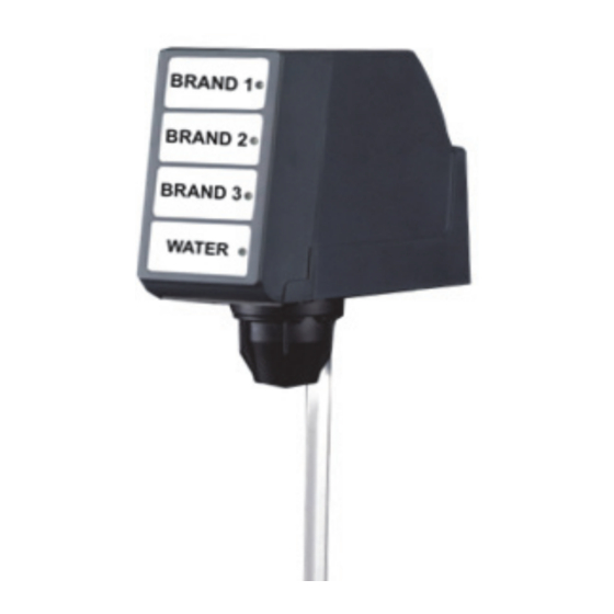
REAR VIEW Figure 1. The Cornelius Prism is capable of dispensing 3 CARBONATED BRANDS / SYRUP OR 3 NON CARBONATED BRANDS / SYRUP and comes with 3 variants as below, refer Table 1 on page 4. NOTE: Both carbonated and non carbonated beverages CANNOT BE DISPENSED IN THE SAME... -
Page 9: Cleaning Instruction
Prism Owner’s Manual Table 1. Part No. Description Sanitary Lever Valves 620069112 Prism, Ceramic regulator, with mounting block and covers Push Button Valves 620069114 Prism, Ceramic regulator, with mounting block and covers Optifill Lever Valves 620069118 Prism, Ceramic regulator, with mounting block and covers... - Page 10 Prism Owner’s Manual Touch UI: 1x4 Key 1 - Brand 1 Key 2 - Brand 2 Key 3 - Brand 3 Key 4 - Water Figure 3. USH TO ANITARY EVER PTIFILL Bottom Figure 4. NOTE: The switch is located in the upper right hand corner of the back of the valve faceplate.
-
Page 11: How To Check Prism Ratio
Prism Owner’s Manual HECK RISM ATIO CAUTION: Do not expose the capacitive touch module wire to water. Table 2. Step Action Figure 1. Remove the capacitive touch module by lifting it upward and Wires from valve body pulling out. Remove the rear... - Page 12 Prism Owner’s Manual Press a brand to activate the Back Block time dispense into the proper syrup chamber. If the syrup level doesn’t fall within one bandwidth from the noted water level, turn the adjust screw on Syrup 1 Syrup 3...
-
Page 13: Knock Out Kit
ED150BC, ED150BCZ, ED175BC, ED175BCZ, ED200BC, ED200BCZ, ED250BC, ED250BCZ, ED300BC and ED300BCZ NOTE: All IDC Units (Serial #: 62C0912JD002) since 2009 have panels that will accept the PRISM valve. NOTE: All Duraflex units "DF 150/175/200/250" will not accept PRISM valve due to being "hard plumbed". - Page 14 Prism Owner’s Manual Knockout adapter plate P/N 620069489 Punch Tool Front Die Pan Head Phillips 8-32 Screws - 2 Qty Rear Die 3/18-16 Hex Head Bolt Knockout kit P/N-620069490 Figure 11. © 2022, Marmon Foodservice Technologies Inc. - 9 -...
-
Page 15: Knock Out Punch Instructions
Prism Owner’s Manual NOCK UNCH NSTRUCTIONS WARNING: Must wear required PPE and right tools before using the punch out tool. WARNING: Disconnect power to the unit before servicing following all lock out/tag out procedures established by the user. Verify all of the power is off to the unit before any work is performed. - Page 16 Prism Owner’s Manual Valve Mounting Panel Align the 2 dowel pins of the “Rear Die” with Corresponding holes on the “Valve mounting panel”. Rear Die Figure 15. Assemble “Front Die” loaded with “Punch Tool” to “Rear Die”, using 2 Phillip “8-32” screws.
-
Page 17: Installation Instructions
Prism Owner’s Manual INSTALLATION INSTRUCTIONS - P/N 620069489 NOCK DAPTER LATE Sheet Metal adapter plate for mounting prism valve Figure 19. NOCK DAPTER LATE UBING Table 4. 1. Align knock out adapter plate with 4 holes of valve mounting panel from “Front Side”. - Page 18 Prism Owner’s Manual 2. Prepare the tubing assemblies. Rear Side 90° Long Fittings Oetiker Clamp 90° Short Fittings Insulation Tube Figure 21. NOTE: Check the O-rings on the 90° fittings for damage and replace if necessary. NOTE: Apply Dow 111 or equal lube on the O-rings prior to install.
-
Page 19: Back Block Installation
Prism Owner’s Manual LOCK NSTALLATION Back Block Back Block Assembly Lock Pin Figure 22. Table 6. Step Action Figure Route the Wire Figure 23. Route the wire & connector through relief hole of rear adapter plate and back block. Figure 24. - Page 20 Prism Owner’s Manual Assemble all the lines with L - fittings on to the knock out adapter plate and Figure 25. 3. Align the back block inlet ports to the L- fittings and fasten back block to the valve panel using screws removed...
-
Page 21: Valve Installation
Prism Owner’s Manual ALVE NSTALLATION Table 7. Step Action Figure Wires from valve body Rear Cover to Capacitive touch modules Valve Body Slide, open the capacitive touch module. Disconnect the wires from Capacitive Touch module the capacitive touch module. Remove the rear cover Figure 27. - Page 22 Prism Owner’s Manual Gently push the valve body against back block, until rear surface of the valve body is flush with the back block. Figure 29. Lock the valve body and back block together with lock pin. Refer to Table 8 on page 18.
-
Page 23: Locking Valve With Back Block Using Lock Pin
Prism Owner’s Manual OCKING ALVE WITH LOCK SING Table 8. Step Action Figure Align the valve body with back block. Figure 31. Insert the lock pin through the back block and valve body. Figure 32. Publication Number: 548000037 - 18 -... -
Page 24: Connection Diagram
Prism Owner’s Manual Closed Condition Rotate both the spindles in the direction shown to secure the lock pin in position and also to open the flow path of the drink. Open Condition Figure 33. ONNECTION IAGRAM DIP SWITCH OPTIFILL SYRUP 3... -
Page 25: Syrup And Water Maps
Prism Owner’s Manual YRUP AND ATER NOTE: For switch positions, refer figure 4 on page 5. SYRUP 3 SYRUP 1 PLAIN / CARBONATED SYRUP 2 WATER FRONT VIEW FRONT COVER FRONT VIEW REAR VIEW Figure 35. Publication Number: 548000037 - 20 -... -
Page 26: Touch Module And Cover Installation
Prism Owner’s Manual OUCH ODULE AND OVER NSTALLATION Step Action Figure Assemble rear cover. Figure 36. Route the wires from valve body and connect with capacitive touch module, refer Figure 37. Capacitive Touch Module Figure 37. Slide the touch module on the rear cover from top. -
Page 27: Schematics
Prism Owner’s Manual SCHEMATICS LUMBING IAGRAM Figure 40. Publication Number: 548000037 - 22 - © 2022, Marmon Foodservice Technologies Inc. -
Page 28: Wiring Diagram
Prism Owner’s Manual IRING IAGRAM Figure 41. © 2022, Marmon Foodservice Technologies Inc. - 23 - Publication Number: 548000037... -
Page 29: Illustrated Parts List
Prism Owner’s Manual ILLUSTRATED PARTS LIST ALVE SSEMBLY Figure 42. Publication Number: 548000037 - 24 - © 2022, Marmon Foodservice Technologies Inc. - Page 30 Lever Valve Optifill 560003193 Lever Valve Self Serve 84996001 Flow Control Bonnet Assy 620069310 Screw #8-18 X 1/2 Type 25 410 SS 620070153 Plate Retaining Prism Valve 71860292 Retainer Ring 60245001 Flow Adjustment Screw FFV 31525030 O-Ring.174 ID 103CS 60247...
-
Page 31: Prism Decal
Prism Owner’s Manual 620069490 Knock Out Kit (Not Shown In Fig 42) 620069489 Adapter Plate (Not Shown in Fig 42) 620070512 Punch Tool (Not Shown in Fig 42) 620070508 Coke Decal (Not shown in fig 42) RISM ECAL Table 9... - Page 33 Marmon Foodservice Technologies Inc. www.marmonfoodservice.com www.cornelius.com...
Need help?
Do you have a question about the PRISM and is the answer not in the manual?
Questions and answers