Cornelius IDC PRO 255 Service Manual
Hide thumbs
Also See for IDC PRO 255:
- Operator's manual (46 pages) ,
- Installation manual (43 pages) ,
- Service manual (5 pages)

Related Manuals for Cornelius IDC PRO 255


Summary of Contents for Cornelius IDC PRO 255
- Page 1 IDC PRO 255 Service Manual Release Date: Mar, 15 2017 Publication Number: 621058649SER Revision: A Revision Date: Mar, 15 2017 Visit the Cornelius web site at www.cornelius-usa.com for all your Literature needs.
-
Page 2: Contact Information
Commercial Warranty. Cornelius will not be responsible for any repair, replacement or other service required by or loss or damage resulting from any of the following occurrences, including but not limited to, (1) other than normal and proper use and normal... -
Page 3: Table Of Contents
TABLE OF CONTENTS Safety Instructions..............1 Read and Follow ALL Safety Instructions . - Page 4 Syrup Line Cleaning & Sanitizing..........26 Adjusting the Water to Syrup Ratio (BRIX) .
-
Page 5: Safety Instructions
IDC Pro 255 Service Manual SAFETY INSTRUCTIONS ALL S EAD AND OLLOW AFETY NSTRUCTIONS Safety Overview • Read and follow ALL SAFETY INSTRUCTIONS in this manual and any warning/caution labels on the unit (decals, labels or laminated cards). • Read and understand ALL applicable OSHA (Occupational Safety and Health Administration) safety regu- lations and/or national and local codes before operating this unit. -
Page 6: Qualified Service Personnel
IDC Pro 255 Service Manual UALIFIED ERVICE ERSONNEL WARNING: Only trained and certified electrical, plumbing and refrigeration technicians should service this unit. ALL WIRING AND PLUMBING MUST CONFORM TO NATIONAL AND LOCAL CODES. FAILURE TO COMPLY COULD RESULT IN SERIOUS INJURY, DEATH OR EQUIPMENT DAMAGE. -
Page 7: Unit Location
IDC Pro 255 Service Manual OCATION CAUTION: The unit is not designed for a wash-down environment and MUST NOT be placed in an area where a water jet (pres- sure washer) could be used. CAUTION: This appliance is not intended for use by personnel (including children) with reduced physical, sensory or mental capabilities or lack of experience and knowledge, unless given supervision or instruction concerning use of the appli- ance by a person responsible for safety. -
Page 8: System Overview
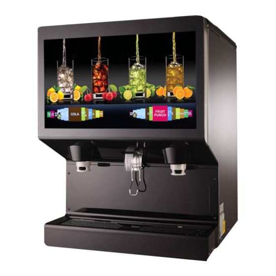
SYSTEM OVERVIEW The Refresh IDC PRO 255 unit solves your ice and beverage service needs in a sanitary, space saving, economical way. It is designed to be manually filled with ice from any remote ice making source. The unit dispenses cubes (up to 1-1/4 inch in size), cube-lets and compressed (not flaked) ice. -
Page 9: Suggested Plumbing Python Bundle
IDC Pro 255 Service Manual Table 1. Cup Clearance 9-3/4 in. (24.77 cm) Ambient Operating Temperature 65 to 95° F (18.3 to 35° C) Figure 1. UGGESTED LUMBING YTHON UNDLE • Water: Insulated for both carbonated recirculation lines and water lines. -
Page 10: Off Cycle Agitation Settings
IDC Pro 255 Service Manual OFF CYCLE AGITATION SETTINGS The off-cycle agitation timer is set from the factory for a 4sec agitation every hour. For soft ice, reset to 3hours off, .5sec on. Figure 2. Publication Number: 621058649SER - 6 -... -
Page 11: E-Box Configuration
IDC Pro 255 Service Manual ONFIGURATION WARNING: Disconnect power to the unit before accessing the E-box. Figure 3. 1. Left hand valve bank MFV board. 2. Right hand valve bank MFV board. 3. 12VDC/24VDC Power Supply. A. 12VDV – Control voltage for MFV boards and computer. -
Page 12: Multi-Flavor Valve Configuration
IDC Pro 255 Service Manual ULTI FLAVOR ALVE ONFIGURATION WARNING: Disconnect power to the unit before accessing the MFV valve. Table 2. Step Action Back-block layout behind each valve bank. Figure 4. MFV Valve Module placed on the back-block. Figure 5. -
Page 13: Disassembly Of An Mfv Valve Module
IDC Pro 255 Service Manual Step Action Each round shutoff (Spindle) needs to be pressed towards down as shown as in Figure 7 to allow fluid to flow past the back-block into the valves. Figure 7 MFV V ISASSEMBLY ALVE ODULE Table 3. -
Page 14: Reassembly Of Mfv Valve
IDC Pro 255 Service Manual Step Action Pull up and rotate valve upwards of bracket to remove from the module. NOTE: Check for all O-rings on bottom of valves. Figure 9. Rotate solenoid counterclockwise and remove to service the solenoid and plunger. -
Page 15: Idc Pro Interactive Touchscreen
IDC Pro 255 Service Manual Step Action Start the block at an angle and push towards down- wards as indicated in Figure 12, ensure that rear flange of the valve fits behind the wall of the carrier bracket. Figure 12. -
Page 16: Touch Controller Removal
IDC Pro 255 Service Manual Touch Controller Removal WARNING: Disconnect power to the unit before accessing displace assembly. Table 5. Step Action Remove touch controller board cover (top right on back of door) by unscrewing the four screws as indi- cated in Figure 16. -
Page 17: Intake Fan Removal
IDC Pro 255 Service Manual Step Action Reverse process for re-installation. Intake Fan Removal Table 6. Step Action Intake Fan Remove the intake fan cover by unscrewing the four screws, pull the cover up front and disconnect the harness. Figure 19. -
Page 18: Exhaust Fan Removal
IDC Pro 255 Service Manual Exhaust Fan Removal Table 7. Step Action Exhaust Fan Remove the exhaust fan cover by unscrewing the four screws. Figure 20. Disconnect the harness connected with fan and pull towards front and take it out as shown in Figure 21. -
Page 19: Single Board Computer
IDC Pro 255 Service Manual Single Board Computer Table 8. Step Action Remove the single board computer cover by unscrewing the four screws. NOTE: The fan connection will be on the board. Figure 22. Disconnect all the harness connected to the board. -
Page 20: Nozzle Diffuser Removal
IDC Pro 255 Service Manual OZZLE IFFUSER EMOVAL Diffuser cleaning or sanitizing is recommended twice weekly. Table 9. Step Action Turn nozzle counterclockwise (left) pull down, the diffuser will stay in position (it is keyed only fits one way). Figure 26. -
Page 21: Drip Tray Cover And Removal
IDC Pro 255 Service Manual OVER EMOVAL Table 10. Step Action Remove the cup rest from the unit. Figure 29. Loosen the thumbscrews on both sides of the drip tray cover. Thumbscrew Figure 30. Remove the drip tray cover from the unit. -
Page 22: Splash Panel Removal
IDC Pro 255 Service Manual PLASH ANEL EMOVAL Table 11. Step Action Open the display panel and remove the thumb-screw holding the upper splash CREW panel as shown in Figure 31 and pull the panel forward and down to remove it. -
Page 23: Connecting Product To The Unit
IDC Pro 255 Service Manual Step Action Release locking tabs outward on both the side as shown in Figure 34.Then lift chute upwards to remove as shown in Figure Figure 34. NOTE: Make sure the pin of ice gate is... -
Page 24: Product Line Connections
IDC Pro 255 Service Manual Product Line Connections To connect the syrup, water and flavor shot lines from the backroom package to the unit, perform the procedure as shown in Table 13. NOTE: If lines are to be cut, mark the line numbers above the cut with a marker. If syrup lines are mixed up they can be mapped later in the control. -
Page 25: Preparing For Operation
IDC Pro 255 Service Manual PREPARING FOR OPERATION ERVICE The Service mode is used to perform all of the maintenance and troubleshooting for the unit. There are three menu levels available depending on the classification of the operator. Figure 38 shows the service mode screen for opera- tors, service mode screen for supervisors and shows the service mode screen for service technicians. -
Page 26: Initial Setup
IDC Pro 255 Service Manual Figure 38 The service screen has a few layout changes, however the access levels remain the same. You have the ability to change your default pass-codes. Row 1 of the service screen shows what will be displayed when the operators level pass-code is entered. - Page 27 IDC Pro 255 Service Manual Table 16. Step Action Input the proper password for your access level (technician) and press Enter. < Enter Figure 40. The Service UI screen is displayed.Press the unit setup button as shown in Figure 41.
- Page 28 IDC Pro 255 Service Manual Table 16. Step Action Press the Brand or Flavor icon that is to be remapped. Figure 43. The Brand Selection screen opens as shown in Figure 44 and you can select the brand to be mapped to the valve location.
-
Page 29: Purging The Syrup Lines
IDC Pro 255 Service Manual Purging The Syrup Lines The purge process is performed as part of the “Syrup Line Cleaning & Sanitizing” section on page 26. If a BIB con- tainer is replaced, the syrup lines need to be purged and sanitized. To purge the lines, perform the procedure in Table Table 17. -
Page 30: Syrup Line Cleaning & Sanitizing
IDC Pro 255 Service Manual Table 17. Step Action Valve Purge The Unit setup screen is displayed. Press the Valve Purge button as shown in Figure 48 Figure 48. The Valve Purge screen is displayed. Select up to 4 syrup and 2 water at a time, per side, to purge. -
Page 31: Adjusting The Water To Syrup Ratio (Brix)
IDC Pro 255 Service Manual Step Action Fill a suitable bucket with a soap solution. Submerge all disconnects (gas and liquid) in the soap solution and then clean them using a nylon bristle brush. (Do not use a wire brush.) Rinse with clean, potable water. - Page 32 IDC Pro 255 Service Manual Table 19. Step Action Display the keypad screen by tapping each cor- ner of the video screen Starting in the upper right corner (1) and continuing to tap each corner in a Counter clockwise direction in a sequence of 1,2,3 and 4 as shown in Figure 53.
- Page 33 IDC Pro 255 Service Manual Table 19. Step Action Select the Brix setup screen as shown in Figure 56. BRIX SETUP Figure 56. All instructions and volumes below are based on the pour rate of 3oz/sec Figure 57. Place a graduated cylinder under the valve.
-
Page 34: Cleaning Interior Surfaces
IDC Pro 255 Service Manual Water Valves Flavor Shots Syrup Valves (White) (Purple) (Black) (Same layout as opposite side) Figure 58. Cleaning Interior Surfaces As part of the monthly cleaning and sanitizing the hopper, perform the procedure in Table 20. - Page 35 IDC Pro 255 Service Manual Table 20. Reassemble agitator assembly. Take special care to ensure that the thumbscrew is tight. Figure 61. Using a mechanical spray bottle filled with sanitizing solution, spray the entire interior and the agitator assembly. Allow them to air dry.
-
Page 36: Unit Operation
IDC Pro 255 Service Manual Table 20. With a nylon bristle brush or sponge, clean the inside of the ice chute, gasket, and cover with soap solution and rinse thor- oughly to remove all traces of detergent. Figure 64. Re-assemble the ice chute assembly. -
Page 37: Unit Shutdown/Restart
IDC Pro 255 Service Manual HUTDOWN ESTART The unit can be shutdown by entering the service UI at any level and selecting the “shutdown” icon. To shut down or restart the unit, perform the procedure in Table 22. Table 22. -
Page 38: Updating Software Revisions
IDC Pro 255 Service Manual Table 22. Step Action Press the Shutdown button to start the shutdown process or press the Restart button to restart the unit. Figure 69. Red/Black button on back of screen shown in Figure 70. To prompt screen push button & select Restart or Shutdown. - Page 39 IDC Pro 255 Service Manual Table 23. Step Action Press the Update Software button as shown in Figure 71. UPDATE SOFTWARE Update Software Figure 71. The Update Software screen is displayed. Press the Launch Software Updater button. Figure 72. The Software Updater screen is displayed. Press the Update Software button.
-
Page 40: Editing The Media Playlist
IDC Pro 255 Service Manual Table 23. Step Action The second Update Software screen is displayed. Figure 74. Select the software version to be installed by selecting from the list on the left side of the screen. If the list on the left side of the screen is empty, press the Scan button. - Page 41 IDC Pro 255 Service Manual Table 24. Step Action Input the proper password for your access level (techni- cian) and press Enter. < Enter Figure 76. This will take you to the Service UI screen. Figure 77. This is where you can access the videos (Media Play-list) or sales information (Marketing Data).
- Page 42 IDC Pro 255 Service Manual Table 24. Step Action First, to manipulate the play-list and their schedule. A new play-list can be added by selecting the second button on the bottom left (with the + symbol). This will add a new play-list in addition to the default play-list. The times when it starts playing and finishes can be adjusted by dragging the play and stop handles left and right.
- Page 43 IDC Pro 255 Service Manual Table 24. Step Action All the videos or images currently on the machine are shown on the right. A USB stick that is connected to any of the (3) available ports will be displayed on the left.
-
Page 44: Plumbing Diagram
IDC Pro 255 Service Manual LUMBING IAGRAM Figure 83. S - Syrup Line. F - Flavor Line. A - Ambient Line. Publication Number: 621058649SER - 40 - © 2016, Cornelius Inc. -
Page 45: Wiring Diagram
IDC Pro 255 Service Manual IRING IAGRAM Figure 84. © 2016, Cornelius Inc. - 41 - Publication Number: 621058649SER... -
Page 46: Troubleshooting
IDC Pro 255 Service Manual TROUBLESHOOTING WARNING: Only trained and certified electrical, plumbing and refrigeration technicians should service this unit. ALL WIRING AND PLUMBING MUST CONFORM TO NATIONAL AND LOCAL CODES. FAILURE TO COMPLY COULD RESULT IN SERIOUS INJURY, DEATH OR EQUIPMENT DAMAGE. - Page 47 IDC Pro 255 Service Manual NOTE: Contact your local syrup or beverage equipment distributor for additional information and troubleshooting of beverage system. © 2016, Cornelius Inc. - 43 - Publication Number: 621058649SER...
- Page 48 IDC Pro 255 Service Manual Publication Number: 621058649SER - 44 - © 2016, Cornelius Inc.
- Page 50 Cornelius Inc. www.cornelius-usa.com...
Need help?
Do you have a question about the IDC PRO 255 and is the answer not in the manual?
Questions and answers