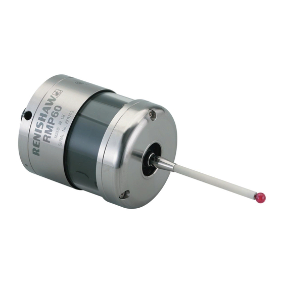
Renishaw RMP60 Installation Manual
Radio machine probe
Hide thumbs
Also See for RMP60:
- Installation manual (68 pages) ,
- Installation and user manual (47 pages) ,
- Quick start manual (48 pages)

Subscribe to Our Youtube Channel
Related Manuals for Renishaw RMP60


Summary of Contents for Renishaw RMP60
- Page 1 Installation guide H-5742-8504-01-A (Beta Site only) RMP60 - radio machine probe Draft copy 09/07/12...
- Page 2 © 2012 Renishaw plc. All rights reserved. This document may not be copied or reproduced in whole or in part, or transferred to any other media or language, by any means, without the prior written permission of Renishaw plc. The publication of material within this document does not imply freedom from the patent rights of Renishaw plc.
-
Page 3: Table Of Contents
RMP60 basics . . . . . . . . . . . . . . . . . . . - Page 4 Performance envelope when using the RMP60 with the RMI or RMI-Q . . . . . . . . . . . . . . .
-
Page 5: Before You Begin
• neglected, mishandled or inappropriately Trademarks used; or RENISHAW and the probe symbol used in the • modified or altered in any way except with RENISHAW logo are registered trademarks of the prior written agreement of Renishaw. -
Page 6: Patents
RMP60 installation guide Patents Features of the RMP60 probe, and other similar Renishaw probes, are subject of one or more of the following patents and/or patent applications: CN 100466003 JP 2009-507240 CN 101287958 JP 2010-238243 CN 101482402A JP 3967592 EP 0695926... -
Page 7: Ec Declaration Of Conformity
Operation is subject to the following two conditions: Contact Renishaw plc at www.renishaw.com/ rmp60 for the full EC declaration of conformity. 1. This device may not cause harmful interference. 2. This device may accept any interference WEEE directive received, including interference that may cause undesired operation. -
Page 8: Radio Approval
RMP60 installation guide Radio approval Radio approvals Europe: Radio equipment - Canadian warning USA: statements Canada: English Japan: Under Industry Canada regulations, this radio transmitter may only operate using an antenna of China a type and maximum (or lesser) gain approved for the transmitter by Industry Canada. -
Page 9: Safety
Renishaw for any reason, do not return any batteries. The RMP60 has a glass window. Handle with care The use of this symbol on the batteries used in this if broken to avoid injury. - Page 10 RMP60 installation guide Information to the equipment installer All Renishaw equipment is designed to comply with the relevant EC and FCC regulatory requirements. It is the responsibility of the equipment installer to ensure that the following guidelines are adhered to, in order for the product to function in accordance with these regulations: •...
-
Page 11: Rmp60 Basics
RMP60 basics Introduction Getting started Three multicolour probe LEDs provide visual RMP60 is part of a new generation of radio indication of selected probe settings. transmission part probing systems, ideally suited to large machining centres or where line-of-sight For example: between probe and receiver is difficult to achieve. -
Page 12: Trigger Logic
Modes of operation Trigger Logic™ (see Section 4 - Trigger Logic™) The RMP60 probe can be in one of three modes: is a method that allows the user to view and select Standby mode: where the probe is awaiting a all available mode settings in order to customise switch on signal. - Page 13 In ‘radio on’ mode, the switch on time is user selectable 0.5 or 1.0 second maximum when After being switched on, the RMP60 must be on using RMI-Q (selection is made in RMI-Q). for 1 second minimum before being switched off.
-
Page 14: Enhanced Trigger Filter
Enhanced trigger filter NOTES: Probes subjected to high levels of vibration or Multiple probe mode is a function of the RMP60, shock loads may output probe trigger signals as such, the option will not appear when the 'radio without having contacted any surface. The on' option has been selected. -
Page 15: Acquisition Mode
NOTES: Systems using the RMI-Q can be partnered with up to four RMP60s manually. Alternatively this can be achieved by using ReniKey; a Renishaw machine macro cycle which does not require the RMI-Q to be powered cycled. Partnering by ReniKey is not available for RMI. -
Page 16: Rmp60 Dimensions
RMP60 installation guide RMP60 dimensions 50 (1.97) 19 (0.75) Battery cassette Shank switch (optional) A range of probe-ready shanks are available from M4 stylus Renishaw 18° 18° Probe status LED 76 (2.99) Window Dimensions given in mm (in) Stylus overtravel limits Stylus length ±X/±Y... -
Page 17: Rmp60 Specification
RMP60 specification Principal application Workpiece measurement and job set-up on medium to large horizontal, vertical and gantry machining centres, 5-axis machines, twin spindle machines and vertical turret lathes. Dimensions Length 76 mm (2.99 in) Diameter 63 mm (2.48 in) Weight (without shank) With batteries 876 g (30.90 oz) - Page 18 RMP60 installation guide Environment IP rating IPX8 Storage temperature -25 °C to +70 °C (-13 °F to +158 °F) Operating temperature +5 °C to +55 °C (+41 °F to +131 °F) Battery types 2 x AA 1.5 V alkaline or 2 x AA 3.6 V Lithium Thionyl Chloride Battery reserve life Approximately one week after a low battery warning is first given.
-
Page 19: System Installation
This allows easy installation, either inside or outside the machine enclosure. Coolant and swarf residue accumulating on the RMP60 and RMI or RMI-Q may have a detrimental effect on transmission performance. Wipe clean as often as is necessary to maintain unrestricted transmission. -
Page 20: Performance Envelope When Using The Rmp60 With The Rmi Or Rmi-Q
RMP60 with the RMI or RMI-Q Performance envelope RMP60 / RMI or RMI-Q positioning The RMP60 and RMI or RMI-Q must be within The probe system should be positioned so that the optimum range can be achieved over the full each other's performance envelope as shown travel of the machine's axes. -
Page 21: Preparing The Rmp60 For Use
Preparing the RMP60 for use Fitting the stylus 1,8 Nm – 2,2 Nm (1.3 lbf.ft – 1.6 lbf.ft) M-5000-3707 Draft copy 09/07/12... - Page 22 NOTE: Must be used with steel styli. For optimum metrology performance do not use a weak link with ceramic or carbon fibre styli. Fitting stylus with weak link onto RMP60 In the event of excessive stylus overtravel, the weak link is designed to break, thereby protecting the probe from damage.
-
Page 23: Installing The Batteries
Installing the batteries NOTES: See Section 5 - Maintenance for a list of suitable battery types. Ensure the product is clean and dry before inserting batteries. Do not allow coolant or debris to enter the battery compartment. When inserting batteries, check that the battery polarity is correct. -
Page 24: Mounting The Probe On A Shank (Or Machine Table)
Mounting the probe on a shank (or machine table) NOTE: In instances where the RMP60 is to be used with a shank switch, it will be necessary to remove the plug from the rear of the probe using pliers. This should then be substituted with the bobbin (A‑4038‑0303). -
Page 25: Stylus On-Centre Adjustment
Stylus on-centre adjustment NOTES: During adjustment, care must be taken not to (x 4) rotate the probe relative to the shank, as damage to the bobbin (A-4038-0303) can occur where fitted. 1 Nm If a probe and shank assembly is dropped, it must (0.74 lbf.ft) be rechecked for correct on-centre adjustment. -
Page 26: Stylus Trigger Force And Adjustment
Stylus trigger force is set by Renishaw. The user should only adjust trigger force in special circumstances e.g. where there is excessive machine vibration or insufficient force to support the stylus weight. -
Page 27: Calibrating The Rmp60
Calibrating the RMP60 • calibrating either in a bored hole or on a turned diameter of known position; Why calibrate a probe? • calibrating either in a ring gauge or on a datum sphere; A spindle probe is just one component of the •... - Page 28 RMP60 installation guide 3.10 This page left intentionally blank Draft copy 09/07/12...
-
Page 29: Trigger Logic
Trigger Logic™ Reviewing the current probe settings LED check > 5 s Key to the symbols LED short flash LED long flash Switch on method Radio on Shank on Spin on (omitted if multiple probe mode is selected) or Switch off method (omitted for shank on) Radio off or Short timeout Medium timeout... -
Page 30: Multiple Probe Settings
RMP60 installation guide Multiple probe settings Deflect the stylus for less than 4 seconds to cycle to the next setting. Multiple probe mode Mode off Mode on Machine 1 Machine 2 Machine 3 Machine 4 Machine 5 Machine 6 Machine 7... -
Page 31: Probe Settings Record
On (20 ms) Hibernation mode On (30 s) ✔ setting On (5 s) Multiple probe mode Off (factory set) ✔ On (machine number) See "Multiple probe settings" Factory settings are for kit (A-5742-0001) only. Draft copy 09/07/12 RMP60 serial no ........ -
Page 32: Changing The Probe Settings
RMP60 installation guide Changing the probe settings > 5 s Insert the batteries or, if they have already been installed, remove them for five seconds and then refit them. Following the LED check, immediately deflect the stylus and hold it deflected until five red flashes... - Page 33 RMI installation guide (H-4113-8554) or the RMI-Q installation guide (H-5687-8504). NOTE: To partner an RMP60 with an RMI please NOTE: To partner an RMP60 with an RMI-Q see "RMP60 – RMI partnership". Once acquisition please see "RMP60 – RMI-Q partnership". Once...
-
Page 34: Rmp60 - Rmi Partnership
Further partnering is only required if either the RMP60 or RMI is In configuration mode, configure the probe changed, or a system is reconfigured for multiple settings as required until you reach the probes (multiple probe mode). -
Page 35: Rmp60 - Rmi-Q Partnership
RMP60 or RMI-Q is changed. "Acquisition mode" menu, which defaults to "Acquisition mode off". Any RMP60 that is partnered with RMI-Q, but then used with another system, will need to be partnered again when it is brought to the RMI-Q. -
Page 36: Operating Mode
RMP60 installation guide Operating mode LEDs LEDs LEDs flashing flashing flashing green Probe status LEDs LED colour Probe status Graphic hint Flashing green Probe seated in operating mode Flashing red Probe triggered in operating mode Flashing green and blue Probe seated in operating mode – low battery Flashing red and blue Probe triggered in operating mode –... -
Page 37: Maintenance
Further dismantling and repair of Renishaw transmission. equipment is a highly specialised operation, which must be carried out at authorised Renishaw Service Centres. Equipment requiring repair, overhaul or attention under warranty should be returned to your supplier. -
Page 38: Changing The Batteries
RMP60 installation guide Changing the batteries CAUTIONS: Do not leave exhausted batteries in the probe. When changing batteries, do not allow coolant or debris to enter the battery compartment. When changing batteries, check that the battery polarity is correct. Take care to avoid damaging the battery cassette gasket. - Page 39 NOTES: After removing the old batteries, wait more than 5 seconds before inserting the new batteries. Do not mix new and used batteries or battery types, as this will result in reduced life and damage to the batteries. Always ensure that the cassette gasket and mating surfaces are clean and free from dirt before reassembly.
-
Page 40: Diaphragm Replacement
RMP60 installation guide Diaphragm replacement M3 screw RMP60 diaphragms 2.5 mm AF 1 Nm (0.74 lbf.ft) The probe mechanism is protected from coolant Cover and debris by two diaphragms. These provide adequate protection under normal working conditions. Outer You should periodically check the outer diaphragm diaphragm for signs of damage. -
Page 41: Rmp60M System
RMP60M system RMP60M system RMP60M is a special modular version of RMP60. It enables probe inspection of part features inaccessible to RMP60, by fitting selected adaptors and extensions as shown below. See Chapter 8, "Parts list". RMP60M probe module M4 stylus RMP60M extension L200 MA4 90°... -
Page 42: Rmp60M Dimensions
RMP60 installation guide RMP60M dimensions 100/150/200 50.50 (3.94/5.91/7.87) 66.25 (2.61) (1.99) 12.50 (0.49) 40.75 50/100/150 (1.60) (1.97/3.94/5.91) 66.25 (2.61) dimensions mm (in) RMP60M screw torque values 10 Nm to 12 Nm (7.37 lbf.ft to 8.85 lbf.ft) 2.6 Nm (1.92 lbf.ft) 2.6 Nm...
Need help?
Do you have a question about the RMP60 and is the answer not in the manual?
Questions and answers