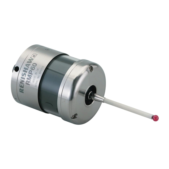
Renishaw RMP60 Installation And User Manual
Radio probe
Hide thumbs
Also See for RMP60:
- Installation manual (68 pages) ,
- Installation and user manual (47 pages) ,
- Quick start manual (48 pages)
Table of Contents
Advertisement
Quick Links
Advertisement
Table of Contents

Related Manuals for Renishaw RMP60


Summary of Contents for Renishaw RMP60
- Page 1 Installation and user’s guide H-2000-5219-01-A RMP60 - radio probe...
- Page 2 The publication of material within this document does not imply freedom Trademarks from the patent rights of Renishaw plc. All brand names and product names used in this document are trade names, service marks, trademarks, or registered trademarks of their respective owners.
- Page 3 Emissions to class A (non-domestic) limits. and that it complies with the requirements of directive (as amended): - 89/336/EEC - Electromagnetic compatibility The above information is summarised from the full EC declaration of conformity. A copy is available from Renishaw on request.
- Page 4 Keep system components clean and treat the must be returned to your supplier. No claims probe as a precision tool. will be considered where Renishaw equipment Patent notice has been misused, or repairs or adjustments have been attempted by unauthorised persons.
-
Page 5: Table Of Contents
Contents Contents Typical probe system with radio RMP60 batteries ........... 17 transmission ............ 4 Battery life expectancy ......... 19 System performance ........5 RMP60/shank mounting ....... 21 Operating envelope ......... 6 Stylus on-centre adjustment ......22 RMP60 features ..........7 Stylus trigger force adjustment ..... -
Page 6: Typical Probe System With Radio Transmission
Typical probe system with radio transmission Typical probe system with radio transmission CNC machining centre spindle Interface mounting bracket RMP60 C N C inspection probe machine control Optional - PSU3 power supply unit Probe status LEDs Typical tool setting probe... -
Page 7: System Performance
RMP60 signal transmission range. Temperature PSU3 Coolant and swarf residue accumulating on the RMP60 and RMI may have a detrimental effect -10 °C to 70 °C Storage on transmission performance. Wipe clean as (14 °F to 158 °F) often as is necessary to maintain unrestricted 5 °C to 50 °C... -
Page 8: Operating Envelope
Operating envelope Operating envelope Range metres (feet) RMP60 probe + RMI OPERATING AND SWITCH ON/OFF RMP60 and RMI must be within each others 75° 15 (49) operating envelope shown. 60° 90° 75° 75° 10 (33) 60° 60° 45° 45° 45°... -
Page 9: Rmp60 Features
RMP60 features RMP60 features Dimensions mm (in) 50 (1.97) 19 (0.75) A range of probe ready shanks is available from RMP60 window Renishaw upon request M4 stylus 18° 18° Battery cover Ø63 (Ø2.48) 76 (2.99) STYLUS OVERTRAVEL LIMITS Stylus length ±X / ±Y... -
Page 10: Rmp60 Specification
Z direction 4.90 N / 490 gf green operating mode (17.28 ozf) and blue - low battery Flashing Probe triggered in RMP60 IP rating IPX8 red and operating mode blue - low battery RMP60 weight Without batteries (without shank) 855 g (30.16 oz) -
Page 11: Probe Status Led
X / Y Weak link (steel styli only) 18° 18° Fitting stylus with weak Removing a broken Fitting a weak link link onto RMP60 weak link In the event of 2 Nm (1.7 lbf.ft) excessive stylus 5 mm AF overtravel the weak 2 Nm (1.7 lbf.ft) -
Page 12: Modes Of Operation
Modes of operation Modes of operation RMP60 switch-on RMP60 power on/off The RMP60 probe can be in one of three modes: Switch-on options are configurable 1. Stand-by mode - The RMP60 is waiting for - see page 13. a switch-on signal . - Page 13 2. Timer off (time out) Note: (Only applies when radio on/spin on After being turned on, the RMP60 must be mode is selected). on for a minimum of 1 sec (7 sec for spin The RMP60 will time out (12, 33 or off) before being turned off.
-
Page 14: Reviewing Current Probe Settings
Reviewing current probe settings Reviewing current probe settings START Note This menu will be omitted if shank Batteries removed from probe turn on has been selected Insert batteries: note the LED sequence, which follows the form below SWITCH OFF METHOD setting Short Medium Long... -
Page 15: Configuration Using Trigger Logic
Configuration using trigger logic Configuration using trigger logic START Note This menu will be omitted if shank Remove batteries from probe. turn on has been selected Hold stylus deflected and insert batteries. Release the stylus only after 15 seconds. SWITCH OFF METHOD menu The current probe settings review Deflect the stylus (>0.5 sec) to sequence, detailed on page 12 will... - Page 16 Settings record table ACQUISITION MODE ACQUISITION MODE Switch on Radio method Shank Once configuration is complete, leave the RMP60 in triggered for 20 sec to save Spin configuration and go to stand-by. Radio/spin Switch off method Return to Short time out...
-
Page 17: System Setup/Establishing Rmp60/Rmi Partnership
6. RMI pattern will change to red & yellow configuration using trigger logic. flashing when it acquires the RMP. 1. Use trigger logic to set RMP60 turn on/ off 7. Allow ~10 seconds for both RMP60 and modes as desired. - Page 18 RMI to be partners with more than one RMP60. It is possible for an RMP60 to be partners with more than one RMI, but the system will not work correctly if more than one partner RMI is...
-
Page 19: Rmp60 Batteries
Only use specified batteries. Do not mix new and used batteries or battery types, as this will result in reduced life and Clean and dry RMP60 with a cloth or paper towel damage to the batteries. before removing battery cover. Where the... - Page 20 RMP60 batteries Battery cover Batteries 2 x AA DO NOT leave exhausted batteries in probe Please dispose of exhausted batteries DO NOT allow coolant or debris to enter the in accordance with local regulations. battery compartment Do not dispose of batteries in fire.
-
Page 21: Battery Life Expectancy
(page 12). typically the probe will continue to operate for In order to achieve stated radio stand-by life, approximately 2 weeks after a low battery the RMP60 must be in range of powered warning is first indicated. partner RMI. CONTINUOUS... - Page 22 Part number will change to constant red. 596-602, 201-9438, Radio Shack 23-037 Battery specification The RMP60 requires two identical AA size Manufacturer Part number batteries, individually rated at a voltage of Saft LS 14500 between 1.2 V and 3.6 V.
-
Page 23: Rmp60/Shank Mounting
6. Tighten screws B to 6-8 Nm (4.4- 5.9 lb.ft) (Partially tighten screws B to 2 - 3 Nm (1.47 - 2.2 lbf.ft), if RMP60 is to be on-centre adjusted). 7. The RMP60 assembly is ready for use. -
Page 24: Stylus On-Centre Adjustment
20 µm, fully tighten screws B to 6 - 8 Nm (4.4 - 5.9 lbf.ft). 10. For final centering use screws A to move the RMP60, progressively slackening on one side and tightening the opposite screw, as the final setting is approached, using two hexagon keys. -
Page 25: Stylus Trigger Force Adjustment
Spring force within the probe causes the stylus to sit in one unique position, and return to this position following each stylus deflection. Stylus trigger force is set by Renishaw. The user should only adjust trigger force in special circumstances e.g. excessive machine vibration or insufficient force to support the stylus weight. -
Page 26: Probe Moves
Probe moves Probe moves Probe trigger With a double touch sequence the first move finds the surface quickly. Then the probe is backed off A probe trigger signal is generated when the to a position clear of the surface, before making probe’s stylus is driven against a surface. - Page 27 Probe interface signals 1. Error signal delay Probing cycles are available from Renishaw A delay of 28 ms maximum for the RMI, will elapse between an error occurring and the Calibrating a system output indicating error.
-
Page 28: Software Requirements
Software requirements Software requirements Verify your software Probing cycles and features are machine Does your software have suitable calibration software dependant. Good software will allow the routines which compensate for stylus on-centre following functions : errors? If not, you must set the probe stylus on-centre mechanically. -
Page 29: Typical Probe Cycles
Typical probe cycles for machining centres Typical probe cycles for machining centres Simple to use canned cycles for basic features Inspection probe Inspection calibration Bore and boss measure Probe XY offset calibration Web and pocket measure Stylus ball radius calibration Internal and external corner find Probe length calibration... - Page 30 Bore and boss on PCD 4th axis measure Angled web and pocket measure Feature-to-feature measure Angled surface measure Macro software for use with the RMP60 is available from Renishaw for the majority of major controller types, please see Parts list (page 39).
-
Page 31: Diaphragm Replacement
Diaphragm replacement Diaphragm replacement RMP60 DIAPHRAGMS OUTER DIAPHRAGM INSPECTION The probe mechanism is protected 1. Remove the stylus. from coolant and debris by two diaphragms. 2. Undo three M3 front cover screws These provide adequate protection under and remove the front cover normal working conditions. - Page 32 Diaphragm replacement OUTER DIAPHRAGM REPLACEMENT 6. Fit new diaphragm over centre. M3 screw 7. Locate outer edge of diaphragm to rest 2.5 mm AF on outer edge of inner diaphragm. 1 Nm (0.74 lbf.ft) 8. Refit front cover and M3 screws. 9.
-
Page 33: Fault Finding
Fault-finding Fault finding - If in doubt, consult your probe supplier. Symptom Cause Action RMP60 fails to switch on Dead batteries Change batteries Batteries incorrectly Check/change batteries inserted Probe out of range Check position of RMI, see (does not apply to spin-on performance envelope. - Page 34 Fault-finding Symptom Cause Action RMP60 fails to switch off Incorrect switch off method Check configuration and alter configured. as required. No RMI ‘start/stop’ signal Check for green start LED (applicable only in radio off, Check wiring. mode, but not applicable in Heidenhain mode).
- Page 35 Review program. path. No LED’s lit on RMI No power to RMI Check wiring RMI status LED’s do not Radio link failure – RMP60 Check position of RMI, correspond to RMP60 out of RMI range. see performance envelope. status LED’s...
- Page 36 Fault-finding Symptom Cause Action RMI error LED lit during Probe timed out Change setting. probing cycle (continued) Review turn off method Probe out of range Check position of RMI, see performance envelope. RMI error LED illuminated Probe not switched on. Check configuration and alter during intended probe cycle as required...
- Page 37 Fault-finding Symptom Cause Action Poor measurement Debris on part or stylus. Clean. results. Recalibrate if probe was calibrated with debris on stylus. Repeatability of probe Verify by repeated toolchange into spindle. and single point move. Loose probe to shank Check and tighten as mounting or stylus.
-
Page 38: Appendix 1 Rmi
Appendix 1 Appendix 1 RMI (RADIO MACHINE INTERFACE) The RMI is fully described in User's guide H-2000-5220 A visual indication of system status is provided by light emitting diodes (LED's). Status is continuously updated and indication is provided for START, LOW BATTERY, PROBE STATUS, ERROR, SIGNAL STRENGTH LED LIGHT SIGNALS 1. - Page 39 Appendix 1 3. Error Notes. Error, other outputs may 1. The probe status LED will always be be incorrect. illuminated when power is present, there is no power present LED/light. Off: No Error. 2. All the indicators report the status of the 4.
-
Page 40: Parts List
Please quote the Part no. when ordering equipment. Type Part no. Description RMP60 A-4113-0001 RMP60 probe with batteries, tool kit and User’s guide (set to radio on/radio off). RMP60 A-4113-0002 RMP60 probe with batteries, tool kit and User’s guide (set to radio on/time off). - Page 41 — For complete listing please see Renishaw Styli guide. Part no. H-1000-3200. Software — For complete list of Renishaw software for machine tools please see Data sheet. Part no. H-2000-2289. Shanks — For complete listing please see Renishaw Data sheet...
- Page 42 Renishaw plc +44 (0)1453 524524 New Mills, Wotton-under-Edge, +44 (0)1453 524901 Gloucestershire, GL12 8JR uk@renishaw.com United Kingdom www.renishaw.com For worldwide contact details, please visit our main website at www.renishaw.com/contact *H-2000-5219-01-A*...
Need help?
Do you have a question about the RMP60 and is the answer not in the manual?
Questions and answers