Sign In
Upload
Manuals
Brands
Burkert Manuals
Measuring Instruments
FLOWave L 8098
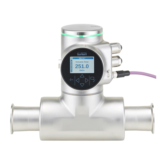
Burkert FLOWave L 8098 Manuals
Manuals and User Guides for Burkert FLOWave L 8098. We have
2
Burkert FLOWave L 8098 manuals available for free PDF download: Quick Start Manual
Burkert FLOWave L 8098 Quick Start Manual (90 pages)
SAW Flowmeter
Brand:
Burkert
| Category:
Measuring Instruments
| Size: 1 MB
Table of Contents
Table of Contents
3
1 The Quickstart
7
Symbols Used
7
Definition of the Term Device
7
Definition of the Term Büs
8
Validity of the Quickstart
8
2 Intended Use
9
Device with Atex Certification
9
3 Basic Safety Information
10
4 General Information
12
Manufacturer's Address and International Contacts
12
Warranty Conditions
12
Information on the Internet
12
5 Description
13
Device Variants
13
Wi-Fi Module
15
Unlocking Magnetic Key
15
Type Labels
16
Adhesive Labels
16
Laser Marking
18
Marking with the Mac Address
18
Certification Markings
18
Marking of the Unique Serial Number (Usn)
19
Device Status Indicator
19
6 Technical Data
20
Operating Conditions
20
Conformity to Standards and Directives
21
Conformity to the Pressure Equipment Directive
21
UL Certification
21
EHEDG Certification
22
ATEX Certification
22
Fluid Data
23
Measurement Data
25
Electrical Data
26
Mechanical Data
28
Specifications of the Ethernet Industrial Communication
29
Modbus TCP Protocol
29
PROFINET Protocol
30
Ethernet/Ip Protocol
31
Ethercat Protocol
32
7 Installation in a Pipe
33
Safety Instructions
33
Additional Documentation
34
Preparing the Device before Installation into the Pipe
34
Changing the Position of the Transmitter on the Sensor
34
Switching Positions of the Blind Cover and the Display Module
38
Recommendations for the Installation into the Pipe
41
Installing the Device into the Pipe
44
Before Installing the Device into the Pipe
44
Installing a Device with Clamp Connections
44
Installing a Device with Flange Connections
44
8 Electrical Installation
45
Safety Instructions
45
Additional Documentation
47
Connecting the Device to a Power Supply
47
Connecting the Device to a Büs / Canopen Network
48
Activating the Device Internal Termination Resistor
49
Specifications of the Cables for the M20X1,5 Cable Glands (Device Variant with Cable Glands)
50
Specifications of the Conductors for the 12 Push-In Terminal Strip
50
Terminal Assignment of the 12 Push-In Terminal Strip
51
Opening the Front of the Transmitter
52
Wiring the Device through the M20X1,5 Cable Glands in Stainless Steel (Device Variant with Cable Glands)
53
Wiring the Device through the M20X1,5 Cable Glands in Nickel Plated Brass (Device Variant with Cable Glands)
55
Connecting The Functional Earth (Device Variant With Two M20X1,5 Cable Glands)
57
Connecting the Device to a 12
58
Variant With Cable Glands)
59
Wiring Output 2 (Digital) and Output 3 Configured as a Digital Output (Device Variant with Cable Glands)
60
Knowing the Status of the Ethernet Network (Device Variant with Two 4-Pin M12 Female Connectors - Ethernet Device Variant)
61
Specifications Of The Cables And Conductors For The 4-Pin M12 Female Connectors
62
Connecting the Device to an Ethernet Network (Device Variant with Two 4-Pin M12 Female Connectors - Ethernet Device Variant)
62
Connecting the Functional Earth (Device Variant with Two 4-Pin M12 Female Connectors - Ethernet Device Variant)
63
9 How to Do the Settings
64
Safety Instructions
64
Available Software to Do the Settings
64
Preparing the Bürkert Communicator Software
64
Display Module: Description of the User Interface
66
Description of the Display
67
How to Use the Touch Sensitive Keys
68
Minimum and Maximum Values When Entering a Numerical Value
68
Available Login User Levels
68
Default Settings
69
Menu Structure
70
Opening or Closing the Context Menu in any View (Display Module Only)
71
Adding Your Own Context Menu Items (Shortcuts, Display Module Only)
72
Reading out the Messages Generated by the Device
73
Changing the Login User Level if the Adjustment Is Not Protected through Passwords
73
Changing the Login User Level if the Adjustment Is Protected through Passwords
74
Installer Bürkert
74
Reading out the Access Path to a Menu Item (Display Module Only)
75
How to Navigate in the Menus and to Adjust Values
75
Adjusting a Percentage or Selecting a Value in a List
75
Navigating in a Wizard and Adjusting Numbers
76
Setting Negative or Positive Numbers
77
Entering a Name
78
Activating or Deactivating a Feature
79
Doing the Quick Start Adjustments When Energizing the Device for the First Time (Display Module Only)
80
Changing The Type Of Output 3
81
10 Maintenance and Troubleshooting
82
Safety Instructions
82
Information On Returning The Device To The Manufacturer Or To The Reseller
83
Cleaning The Outer Surface Of The Device
83
Cleaning In Place (Cip) Of The Device
83
Sterilisation In Place (Sip) Of The Device
84
Troubleshooting When No Message Is Displayed
84
Troubleshooting When A Message Is Displayed
85
11 Spare Parts and Accessories
86
12 Packaging, Transport
87
13 Storage
87
14 Disposal of the Device
87
Advertisement
Burkert FLOWave L 8098 Quick Start Manual (80 pages)
Brand:
Burkert
| Category:
Measuring Instruments
| Size: 3 MB
Table of Contents
Table of Contents
3
The Quickstart
7
Symbols Used
7
Definition of the Term Device
8
Definition of the Term Büs
8
Validity of the Quickstart
8
Intended Use
9
Device with ATEX / Iecex Certification
9
Basic Safety Information
10
General Information
12
Manufacturer's Address and International Contacts
12
Warranty Conditions
12
Information on the Internet
12
Description
13
Device Variants
13
Wi-Fi Module
15
Unlocking Magnetic Key
15
Type Labels
16
Adhesive Labels
16
Laser Marking
18
Marking with the MAC Address
18
Certification Markings
18
Marking of the Unique Serial Number (USN)
19
Device Status Indicator
19
Technical Data
20
Operating Conditions
20
Conformity to Standards and Directives
21
Conformity to the Pressure Equipment Directive
21
UL Certification
21
EHEDG Certification
22
ATEX / Iecex Certification
22
Liquid Data
23
Measurement Data
25
Volume Flow Rate
25
Temperature
25
Differentiation Factor
25
Acoustic Transmission Factor
26
Density
26
Mass Flow Rate
26
Electrical Data
27
Mechanical Data
29
Specifications of the Ethernet Industrial Communication
29
Installation in a Pipe
30
Safety Instructions
30
Additional Documentation
31
Preparing the Device before Installation into the Pipe
31
Changing the Position of the Transmitter on the Sensor
31
Switching Positions of the Blind Cover and the Display Module or the Wi-Fi Module
35
Recommendations for the Installation into the Pipe
38
Installing the Device into the Pipe
41
Before Installing the Device into the Pipe
41
Installing a Device with Clamp Connections
41
Installing a Device with Flange Connections
41
Installing a Device with External-Threaded Connections According to DIN 11851 Series a for Pipes According to DIN 11850
42
Electrical Installation
43
Safety Instructions
43
Additional Documentation
45
Connecting the Device to a Power Supply
45
Connecting the Device to a Büs / Canopen Network
46
Activating the Device Internal Termination Resistor
48
Specifications of the Cables for the M20X1.5 Cable Glands (Device Variant with Cable Glands)
48
Specifications of the Conductors for the 12 Push-In Terminal Strip
48
Terminal Assignment of the 12 Push-In Terminal Strip
49
Opening the Front of the Transmitter
50
Wiring the Device through the M20X1.5 Cable Glands in Stainless Steel (Device Variant with Cable Glands)
51
Wiring the Device through the M20X1.5 Cable Glands in Nickel Plated Brass (Device Variant with Cable Glands)
53
Connecting The Functional Earth (Device Variant With Two M20X1.5 Cable Glands)
56
Connecting the Device to a 12
57
Wiring Output 1 (Analogue) and Output 3 Configured as an Analogue Output (Device Variant with Cable Glands)
58
Wiring Output 2 (Digital) and Output 3 Configured as a Digital Output (Device Variant with Cable Glands)
59
Knowing the Status of the Ethernet Network (Device Variant with Two 4-Pin M12 Female Connectors - Ethernet Device Variant)
60
Specifications Of The Cables And Conductors For The 4-Pin M12 Female Connectors
61
Connecting the Device to an Ethernet Network (Device Variant with Two 4-Pin M12 Female Connectors - Ethernet Device Variant)
61
Connecting the Functional Earth (Device Variant with Two 4-Pin M12 Female Con- Nectors - Ethernet Device Variant)
62
How to Do the Settings
63
Safety Instructions
63
Available Software to Do the Settings
63
Connect the Device to the Bürkert Communicator Software
63
Display Module: Description of the User Interface
65
Available Login User Levels
65
Changing the Login User Level if the Adjustment Is Not Protected through Passwords
66
Changing the Login User Level if the Adjustment Is Protected through Passwords
67
Logging out from the Advanced User, Installer or Bürkert User Level
67
Reading out the Access Path to a Menu Item (Display Module Only)
68
Doing the Quick Start Adjustments When Energizing the Device for the First Time (Display Module Only)
68
Changing the Type of Output 3
69
Commissioning
70
Safety Instructions
70
Prerequisites
70
First Commissioning For Measuring The Flow Rate Or For Filling Containers
70
First Commissioning For Detecting A Change Of Liquid In The Pipe
71
First Commissioning For Detecting Bubbles In The Pipe
73
Maintenance and Troubleshooting
74
Safety Instructions
74
Information On Returning The Device To The Manufacturer Or To The Reseller
75
Cleaning The Outer Surface Of The Device
75
Troubleshooting When No Message Is Displayed
75
Troubleshooting When A Message Is Displayed
76
Spare Parts and Accessories
77
Packaging, Transport
78
Storage
78
Disposal of the Device
78
Advertisement
Related Products
Burkert Flowave 8098
Burkert FLOWave S 8098
Burkert FLOWave L
Burkert FLOWave S
Burkert 285877
Burkert 285880
Burkert 286100
Burkert 286212
Burkert 2875
Burkert 287586
Burkert Categories
Control Unit
Controller
Measuring Instruments
Transmitter
Accessories
More Burkert Manuals
Login
Sign In
OR
Sign in with Facebook
Sign in with Google
Upload manual
Upload from disk
Upload from URL