Advertisement
Quick Links
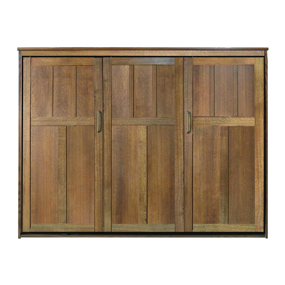
Style: Park City
Size:
Queen, Full, or Twin
Depth:
Storage Head Board
Side Mount with 13" Legs
Type:
WARNING! ALL MURPHY/WALLBED SYSTEMS CONTAIN STORED ENERGY. FAILURE TO USE AND
FOLLOW THESE INSTRUCTIONS DURING THE INSTALLATION PROCESS COULD RESULT IN SEVERE
PERSONAL INJURY TO USER OR DAMAGE TO PRODUCT. PLEASE CONTACT CUSTOMER SERVICE AT
866-725-6401 FOR ANY QUESTIONS.
28
Revision 4.22
Advertisement

Related Manuals for Wilding Wallbeds Park City


Summary of Contents for Wilding Wallbeds Park City
- Page 1 Style: Park City Size: Queen, Full, or Twin Depth: Storage Head Board Side Mount with 13” Legs Type: WARNING! ALL MURPHY/WALLBED SYSTEMS CONTAIN STORED ENERGY. FAILURE TO USE AND FOLLOW THESE INSTRUCTIONS DURING THE INSTALLATION PROCESS COULD RESULT IN SEVERE PERSONAL INJURY TO USER OR DAMAGE TO PRODUCT.
- Page 2 Page intentionally left blank...
- Page 3 Step Ladder Studsensor...
- Page 4 Bed Handles 3/8’’...
- Page 5 23” 23” Finished edge Cut out for room base molding Left Side Board Right Side Board...
- Page 6 Before you proceed, identify which spring type you have received:...
- Page 7 The required number of springs in the Lift Mechanisms varies with the different weights of mattresses. If you purchased your mattress with your bed from Wilding Wallbeds refer to the chart to the right. This will also be a good reference point for mattresses not purchased with your Wall bed.
- Page 8 The required number of springs in the Lift Mechanisms varies with the different weights of Queen mattresses. If you purchased your mattress with your bed from Wilding Wallbeds refer to the Full/Double chart to the right. This will also be a good reference point for mattresses not purchased with your Wall bed.
- Page 9 Hardware needed for next step Page 7...
- Page 10 Locate and Identify the Following Parts Rear Stretcher Head Board Bottom Identifiers Identifiers -Boards are 5” wide (length depends on size of the bed). -Board 7.5” wide (length depends on size of the bed). -4 Pre-installed Cam Fittings per Stretcher 2 on either end. -2.3/8”...
- Page 11 Hardware needed for next step Step 6: Screw 11 Connecting Bolts into the holes provided in the Bridge Board.
- Page 13 Step 8: Begin assembly of the Bed Cabi- net face down with the bottom of the bed nearer the wall to which it will be installed as illustrated. Connecting the Head Board, Front and Rear stretchers see illustration.
- Page 14 Step 10: Install the hinged storage door unit as illustrated. Helpful hint: Lift the center section to get the unit posi- tioned correctly...
- Page 17 Studs in wall...
- Page 18 Important note: It is critical to orient the Bed Face panels and the Mattress Rails in the next 5 steps correctly. All of the render- ings (drawings) in the next 5 steps assume that you are looking away from the wall you just installed the Bed Cabinet against in the previous step.
- Page 19 Step 18: From hardware pack 3 locate the hardware shown above. Finger tighten the hardware as shown in illustration 7 connecting the Outer Side rail to a Head/Foot rail using a 4 hole corner bracket. Note the lower hole on each Head/Foot rail uses the Leg Stop with the longer screw (1 1/4”...
- Page 20 Frame positioned evenly side to side with wood face panels protruding by approximately 1” on either side. BIRDS EYE (TOP) VIEW Page 18...
- Page 21 Hardware and parts needed for next steps Wood Mattress Support...
- Page 22 Step 24 ; Attach the Buckle Strap used for holding the mattress in place when the bed is closed. First remove one of the 5/8” Pan head screws that attaches the rail to the Face Panels on each Side Rail of the frame at about 18”...
- Page 23 Step 25: As illustrated below, insert the Allen Head Bolt through bolt hole # 1 and tighten it down securely using a Nylock Nut. Now insert a 5/16” x 1” Hex Head bolt through hole # 3 and thread the Nylock nut ONLY UNTIL THE NUT IS FLUSH WITH THE END OF THE BOLT.
- Page 24 WARNING: There is tremendous force involved in the next step, do not place hands be- tween the front of the side boards and the tension arms as you set the mechanism. Helpful hint: As you start to draw the Tension Arm down with one hand, use the other hand to position the Arm Lock on top of the Hex Nut.
- Page 25 IMPORTANT! As instructed in step 25, Bolt #3 should be loose enough to slip into the notch at the end of the Tension Arm See illustration below. Step 30: Stand the Bed face unit up on its Inner Side Rail. Now with you and your assistant on either side of the Bed unit lift until the # 3 bolt on the Head/Foot Rail is a few inches...
- Page 26 Step 31: Insert a 5/16” x 1” Hex Head bolt through hole #2 and tighten a 5/16” Nylock nut onto the bolt. Now tighten the nut and bolt in hole #3. Repeat step 31 on the other side of the bed unit.
- Page 27 Step 33: When the bed is closed check to see if the gap on either side is the same. If it looks right skip this step. If the gap is not right, meaning that the Bed Face is too close to the Side Board or even touching it at the top on one side it will need to be ad- justed.
Need help?
Do you have a question about the Park City and is the answer not in the manual?
Questions and answers