
Related Manuals for Maxcess MAGPOWR HEB250


Summary of Contents for Maxcess MAGPOWR HEB250
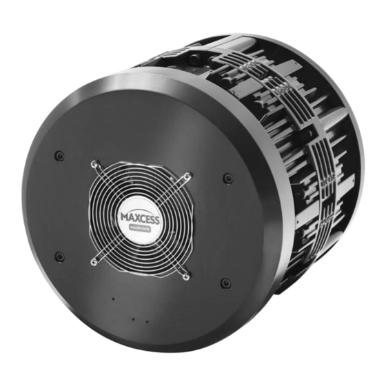
- Page 1 MAGPOWR TENSION CONTROL HEB250 High Efficiency Brake Installation, Operation and Maintenance MI 850A346 1 B...
-
Page 2: Model Number Key
HEB250 User/Installation Manual All of the information herein is the exclusive proprietary property of Maxcess International and is disclosed with the understanding that it will be retained in confidence and will neither be duplicated nor copied in whole or in part nor be used for any purpose other than for which disclosed. - Page 3 (1) If a proximity sensor is selected, then a fan must be selected, and the maximum number of calipers is 5. (2) Listed rotor bores are standard. See Table 1 for complete list of rotors bore diameters. (3) Blank if standard. Example model number: HEB250-4-M-F-P-10 is an HEB250 with (4) ea calipers, “medium”...
-
Page 4: Available Models
Table 1. Part number codes for bore diameter and rotor set screw tightening torques (Highlighted Bores are Standard) Bore Keyway Set Screw Torque Part Code Bore Diameter Keyway Set Screws Units Units Nm [lb-in] 0.7500 inch 3/16 x 3/16 inch 13/16 0.8125 inch... - Page 5 Caliper Positioning Illustrations below represent the positioning of “active” calipers in all possible configurations. All unused “active” caliper positions are filled with “dummy” calipers. Views are top views looking at the front calipers. 2 Calipers 3 Calipers 1 Caliper with or w/o proximity sensor with or w/o proximity sensor with or w/o proximity sensor 4 Calipers...
- Page 6 Dimensions: Figure 2. HEB250 Dimensions www.maxcessintl.com HEB250 Brake MI 850A346 1 B Page 6...
-
Page 7: Safety Information
Safety Information: To ensure safe and problem free installation of the pneumatic brake device, the brake must be properly transported and stored, professionally installed and placed in operation. Proper operation and maintenance will ensure a long service life of the device. Only persons who are acquainted with the installation, commissioning, operation and maintenance of the system and who possess the necessary qualifications for their activities may work on the pneumatic brake. -
Page 8: Basic Safety Information
Basic Safety Information: Proper Use: The HEB brake is intended to produce braking torque proportional to input pneumatic pressure to create web tension in an unwind roll of material. Intended for indoor operation only. Improper Use: Operation outside the technical specifications. Operation in an Ex-area or intrinsically safe area. -
Page 9: Mechanical Installation
Mechanical Installation: WARNING – Danger of injury from crushing. Installation of the brake must be performed only when the machine has been stopped and has been secured from being turned on again. How to mount the brake to the machine frame: Units: mm [inches] Brake assembly may be either directly mounted to the machine frame or mounted to an adapter plate (HEB250BKPLT) with the correct bolt pattern pre-established. - Page 10 Mount the rotor on the shaft without tightening the set screws. Mount one of the caliper mounting halves (halves are symmetrical, so it does not matter which half) to the machine frame using (4) ea M8x1.25 bolts. Tighten bolts to a torque of 40 Nm [29.5 lb-ft].
- Page 11 For brakes WITHOUT a fan shroud remove the existing (2) ea M4, (1) ea M6 screws, and nameplate on the caliper mounting halves. Install the fan finger guard and the nameplate using the previously removed (2) ea M4, and (1) ea M6 screws as shown in the illustration above.
- Page 12 How to mount the brake using adapter plate (HEB250BKPLT): Mount adapter plate to existing safety chucks, chucks, bearing block, or machine frame surface using existing bolt hole patterns in adapter plate or attached to customer supplied bracketry or custom weldments. Proceed to step B in the previous section.
-
Page 13: Electrical Installation
Electrical Installation WARNING – Death or injury can result from electric shocks. Installation of the fan shroud must be performed when there is no electrical power in the system. Never place electrical cables under mechanical strain. Always route wiring in either flexible or rigid conduit. All wiring must comply with the essential requirements of the appropriate standard(s) and is the responsibility of the installer. -
Page 14: Maintenance
Maintenance: WARNING – Danger of injury from crushing. Maintenance and repair tasks on the brake must be performed only when the machine has been stopped and has been secured from being turned on again. Daily – Keep the brake assembly free of dust and debris buildup during shift operation. ... -
Page 15: Replacement Part Kits
Replacement Part Kits: Pad replacement kits. Each kit contains (2) ea pads to fill (1) ea caliper. Model Number Description HEBPKL HEB pad kit for low friction pads (0.21) HEBPKM HEB pad kit for medium friction pads (0.41) HEBPKH HEB pad kit for high friction pads (0.51) Replacement Calipers. - Page 16 Item Description Part Number Back Caliper 712C123-1 Set Screw 78610-002 Piston Seal 25A65-1 Piston Bearing Strip 712C134-1 Piston 712C127-1 Compression Spring 5A349-1 Piston Retaining Plate 712C128-1 Internal Retaining Ring 28098-059 Brake Pad Assembly 145C24-X Figure 5. Back Caliper Assembly Exploded View Item Description Part Number...
-
Page 17: Troubleshooting
Troubleshooting: PROBLEM POSSIBLE CAUSE ACTION No torque or low torque Airline leaking Replace air line Air fitting leaking Replace air fitting Caliper seal leaking Order caliper repair kit. RKHEBCAL One or more pads worn Order pad replacement kits. HEBPKL, HEBPKM, or HEBPKH Fan not running No power to fan Check power supply... - Page 18 Pressure vs. Torque: Torque at 60 psi (414 kPa) lb-in (Nm) Torque at 90 psi (621 kPa) lb-in (Nm) Number of Number of Coefficient of friction of pad Coefficient of friction of pad Calipers Pads Med. High High (0.12) (0.41) (0.51) (0.12) (0.41)
- Page 19 AND AFRICA AND SE ASIA Tel +1.405.755.1600 Tel +86.756.881.9398 Tel +91.22.27602633 Tel +81.43.421.1622 Tel +49.6195.7002.0 asia@maxcessintl.com Fax +1.405.755.8425 Fax +86.756.881.9393 Fax +91.22.27602634 Fax +81.43.421.2895 Fax +49.6195.7002.933 www.maxcess.asia sales@maxcessintl.com info@maxcessintl.com.cn india@maxcessintl.com japan@maxcessintl.com sales@maxcess.eu www.maxcessintl.com www.maxcessintl.com.cn www.maxcess.in www.maxcess.jp www.maxcess.eu © 2018 Maxcess...
Need help?
Do you have a question about the MAGPOWR HEB250 and is the answer not in the manual?
Questions and answers