Table of Contents

Related Manuals for GASTRON GIR3000


Summary of Contents for GASTRON GIR3000
- Page 1 Design, development, production, installation, and servicing of Gas Dectector GIR3000 Instruction Manual Revision: 2.0 device Please read this manual carefully for proper use of the Copyright ⒞GASTRON, Co., LTD. All rights reserved.
- Page 2 Thank you for purchasing the product of us Gastron Co., Ltd. Gastron has been recognized from many consumers for its top quality and ease of use as a professional company of Gas detectors & Gas Monitors. We are constantly researching and striving to help consumers to find with required products nearby and to develop consumer satisfied Gas detectors.
- Page 3 GIR-3000 Instruction Manual This page intentionally left blank PAGE 3 of 44 Rev 2.0, 2012.8.21...
-
Page 4: Table Of Contents
GIR-3000 Instruction Manual TABLE OF CONTENTS 1. Introduction ..................................6 2. Structure ....................................6 3. Specification ..................................7 4. Name of Components and Main features ......................8 4.1. Components ................................8 4.2. Components Description ..........................9 5. Terminal wiring diagram ............................. 11 5.1. - Page 5 GIR-3000 Instruction Manual 11.3. How to Set PROGRAMMABLE MODE ....................27 11.4. How to use Calibration Mode ........................28 11.4.1. Zero Calibration and Span Calibration ..................28 11.5. How to set alarm in Alarm mode ......................30 11.1. How to use Test Mode ..........................33 11.2.
-
Page 6: Introduction
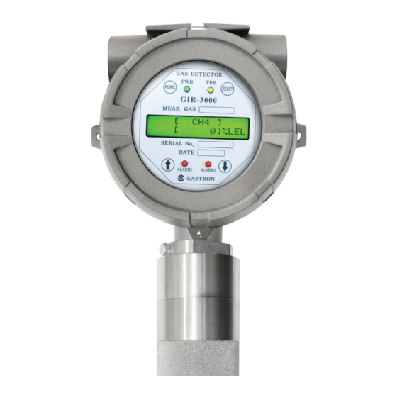
GIR-3000 Instruction Manual 1. Introduction The GIR-3000 is an infrared(IR)-type gas detector that is developed to prevent serious accidents caused by gas leaks by detecting a variety of gases in hazardous areas such as industrial plants, gas storage facilities and factories in the process of producing or consuming flammable gases, CO or CO2. -
Page 7: Specification
GTL-100 (explosion proof LED) Option Rain cover Dimensions 156(W) x 322(H) x 110(D) mm Approx. 3.0kg Weight [Table 1. GIR3000 Specification ] *Note 1) Regarding HART, refer to document on GIR3000 HART® Field Device Specification. PAGE 7 of 44 Rev 2.0, 2012.8.21... -
Page 8: Name Of Components And Main Features
[ALM2] [ALM1] [TRB] [ETH] [-V] [mA] [+V] [VISO] CN11 CN10 TRON TRANSMITTER GASTRON [Figure 1. GIR3000 Components] Name Name HOUSING RESET SWITCH MAIN PCB ↑ SWITCH DISPLAY PCB ↓ SWITCH POWER/SIGNAL TERMINAL EXTERNAL EARTH (4sq ↑) ALARM SIGNAL TERMINAL MOUNT HOLES (2-Ø7) -
Page 9: Components Description
GIR-3000 Instruction Manual 4.2. Components Description Name of component Description Protecting sensors and PCB boards equipped inside the device housing Housing against environmental variations and shocks Amplifying the output signal generated by sensor, converting it to standard output of DC 4-20mA and transmitting converted signal. And Main PCB transmitting isolated RS-485 communication signal and alarm relay contact signal. - Page 10 GIR-3000 Instruction Manual Name of component Description This switch is used to transit mode or adjust number by touching it with ↓(Down) switch magnet bar. The mode will be switched in a backward direction and the number in a decreasing direction. The gas detector must be connected to ground via the external earth External earth point to protect it against external noises or high voltage.
-
Page 11: Terminal Wiring Diagram
Never install, uncover, or manipulate the Detector other than authorized personnel or installation/repair service person from Gastron, or serious loss of life and property damage such as fire or explosion may occur. In addition, check around for explosive Gas or flammable substances, followed by turning OFF before any work. -
Page 12: Main Pcb Configuration
GIR-3000 Instruction Manual 5.2. Main PCB configuration 5.2.1. Main PCB configuration With the Display Part removed, the Main PCB terminal arrangement is shown as the following Figure. [Figure 4. Main PCB terminal arrangement ] Name Description CN12 Power & Output Signal Terminal 4~20mA Source / Sink selection jumper ( ON: Source Type, OFF: Sink Type ) CN11... -
Page 13: Hart Board Configuration
GIR-3000 Instruction Manual 5.2.2. HART Board configuration HART Board consists of Option Board, and is connected using CN5, CN6, CN7 terminals of Main PCB and the HART Board Screw at the top left. [Figure 5. HART Board constituting Main PCB] Name Description HART Board Screw... -
Page 14: Main Pcb Terminal Description And Wiring Method
Note 1) Be sure to use CVVS or CVVSB 2.0sq↑ Shield Cable before Terminal construction. Note 2) Fasten Terminals based on +24V of 2Pin to connect the 4Pin Terminal of existing conventional GIR3000. PAGE 14 of 44 Rev 2.0, 2012.8.21... -
Page 15: Relay Drive Type Wiring Method
GIR-3000 Instruction Manual 5.3.1. Relay drive type wiring method The Relay drive type of GIR-3000 can be operated by two ways. There is De-Energized Mode and Energized Mode. Main PCB is marked A, B silk to set Relay drive type and connect using Jumper as you want Relay drive type. -
Page 16: 20Ma Source Drive Type Wiring Method
GIR-3000 Instruction Manual 5.3.2. 4~20mA Source drive type wiring method Connect 4-20mA Signal Terminal of PLC to ‘mA’ of GIR3000. GND Terminal is used in common with the power. Turn J4 Jumper ON. ※ HART Communicator can be used only in models utilizing HART Option Board. -
Page 17: 20Ma Sink Drive Type Wiring Method
GIR-3000 Instruction Manual 5.3.3. 4~20mA Sink drive type wiring method Connect 4-20mA Sink Output (+) Terminal of PLC to VISO Terminal; and (-) Terminal to ‘mA’ Terminal. Turn J4 Jumper OFF. ※ HART Communicator can be used only in models utilizing HART Option Board. [Figure 9. -
Page 18: Connection Method With Our Main Control Unit
GIR-3000 Instruction Manual 5.3.1. Connection method with our main Control Unit Connect CN12 (VISO,+, mA, -, ET) Connection Terminal of the Gas Detector and the Control Unit with reference to the Figure below. (See product manual for each Control Unit.) GAS DETECTOR VISO POWER... -
Page 19: Standard Type Outside View And Dimensions
GIR-3000 Instruction Manual 6. Standard Type outside view and Dimensions [Figure 10. GIR3000 outside view] PAGE 19 of 44 Rev 2.0, 2012.8.21... -
Page 20: Warning Light Type: Outside View And Dimensions
II 2G Ex dIIC T6 Gb IP65 사 용 온 도: -30°C ~ +70°C 사 용 전 원: 24VDC / 80mA Max. 인 증 번 호: 12-KB2BO-XXXX 2-Ø7 GASTRON [Figure 11. GIR3000 Warning Light type outside view] PAGE 20 of 44 Rev 2.0, 2012.8.21... -
Page 21: Raincover Type: Outside View And Dimensions
GIR-3000 Instruction Manual 8. Raincover type: Outside view and Dimensions 177.41 TRANSMITTER GASTRON [Figure 12. GIR3000 Raincover type outside view] PAGE 21 of 44 Rev 2.0, 2012.8.21... -
Page 22: Menu Configuration Table
GIR-3000 Instruction Manual 9. Menu Configuration Table LEVEL2 LEVEL1 DEFAULT NAME PARAMETER GROUP OF GAS SEL HC/PROPANE/CO/CO2 (GROUP OF GAS SELECT) UNIT & TAG SEL. %/%LEL/PPM/PPB %LEL (UNIT & TAG SELECT) PROGRAMMABLE MODE DECIMAL POINT 0.100/1.00/10.0/100 HIGH SCALE ADJ. 1~10000 (HIGH SCALE ADJUST) PASSWORD SET 00~99... - Page 23 GIR-3000 Instruction Manual LEVEL2 LEVEL1 DEFAULT NAME PARAMETER ALARM1 RELAY CTL [ON / OFF] (ALARM RELAY CONTROL) ALARM1 TIME SET [01]SEC , 0~60 ADJ ALARM2 TYPE SEL. INCREASE/ DECREASE INCREASE (ALARM2 TYPE SELECT) ALARM PROGRAM ALARM2 LEVEL ADJ 1~Full Scale ADJ MODE (ALARM2 LEVEL ADJUST) 0.0~ Adj within 10%...
- Page 24 0000000 [GIR-0001] GIR-0001 DEVICE MODE LONG TAG [GIR-0001-LT] GIR-0001-LT GASTRON DESCRIPTION [ GASTRON GIR3000 ] GIR3000 INFRARED GAS MESSAGE [ IR GAS DETECTOR] DETECTOR FINAL ASSEMB. NUM [ 0 ] , 0~100 ADJ (FINAL ASSEMBLE NUMBER) [Table 8. Menu Configuration Table] PAGE 24 of 44 Rev 2.0, 2012.8.21...
-
Page 25: Detector Activation Flow And Key Operation
GIR-3000 Instruction Manual 10. Detector activation Flow and KEY operation 10.1. Sensor activation Flow Timeout of Level1 and Level2 is 10 seconds, and I hour in the Calibration and Test Mode of Level2. [Figure 13. Detector workflow ] 10.2. Sensor KEY configuration and description Item Name Description... -
Page 26: Detailed Description Of Operational States And Menu
GIR-3000 Instruction Manual 11. Detailed Description of Operational States and Menu 11.1. Initial State (Power On) After wiring power terminal on main PCB has been completed, power can be applied to the detector. Immediately upon applying power, LCD(OLED) will indicate the messages as shown in following figure. Typically, after being powered up, the detector is required to have about 30 minutes to be stabilized. -
Page 27: How To Set Programmable Mode
GIR-3000 Instruction Manual When the measured gas value falls under 90% of preset value, a message “UNDER” will be displayed in every second. In this case, * #[ CH4 ] standard output will fall to under 2mA. [ UNDER]%L ※... -
Page 28: How To Use Calibration Mode
GIR-3000 Instruction Manual 11.4. How to use Calibration Mode The gas detector must be allowed to stabilize prior to use. It requires at least 30 minutes period after being powered up to reach stable condition due to its characteristics. However, management standards may be changeable according to onsite condition. - Page 29 GIR-3000 Instruction Manual When [YES] is shown by touching “↑” or “↓” switch, touching SPAN FUNC switch makes the detector’s mode change to Span CALIBRATION Calibration Mode. This mode enables the user to set standard gas value. The value ...
-
Page 30: How To Set Alarm In Alarm Mode
GIR-3000 Instruction Manual 11.5. How to set alarm in Alarm mode After password has been confirmed, the detector goes into level1 mode. ALARM Select ALARM mode by touching “↑” or “↓” switch. PROGRAM At this moment, if function key is touched, the detector will go ... - Page 31 GIR-3000 Instruction Manual This mode is to set Alarm1 level. The level will increase or decrease whenever “↑” or “↓” switch is touched. When the desired value is shown, touch FUNC switch to set the ALARM1 LEVEL value as Alarm1 value. After that, the detector will go to Alarm Program state.
- Page 32 GIR-3000 Instruction Manual This mode is to set the operational range of Alarm2. The value will increase or decrease whenever “↑” or “↓” switch is touched. In “INCREASE” mode, Alarm1 will be activated on the value of Alarm2 value + Dead band value and deactivated on the value ALARM2 DEAD of Alarm2 value –...
-
Page 33: How To Use Test Mode
GIR-3000 Instruction Manual 11.1. How to use Test Mode After password has been confirmed, the detector goes into level1 mode. TEST Select TEST mode by touching “↑” or “↓” switch. MODE At this moment, if function key is touched, the detector will go ... -
Page 34: How To Use Ir Sensor Data Mode
GIR-3000 Instruction Manual 11.2. How to use IR SENSOR DATA MODE IR Sensor Data Mode is a mode to view current value and state of sensor. In this mode, value and state cannot be modified. After password has been confirmed, the detector goes into level 1 mode. -
Page 35: How To Use Version Mode
GIR-3000 Instruction Manual 11.3. How to use VERSION MODE After password has been confirmed, the detector goes into level1 mode. VERSION Select VERSION mode by touching “↑” or “↓” switch. MODE At this moment, if function key is touched, the detector will go ... -
Page 36: How To Set Maintenance Mode
GIR-3000 Instruction Manual 11.4. How to set Maintenance Mode The operations described in this chapter must not be allowed by general users. ※ After password has been confirmed, the detector goes into level1 mode. MAINTENANC Select MAINTENANCE mode by touching “↑” or “↓” switch. At this moment, if function key is touched, the detector will go ... - Page 37 GIR-3000 Instruction Manual This mode enables user temperature compensating functionality of sensor. Touch “↑” or “↓” switch, then the mode will be alternatively TEMP switched between ON and OFF. COMPENSA In case of setting to be ON, the temperature compensation ...
-
Page 38: How To Configure 485 Modbus
GIR-3000 Instruction Manual This mode is to set functionality of displaying equipment’s temperature and –LEL value. Touch “↑” or “↓” switch, then the mode will be alternatively ENGINEERING switched between ON and OFF. In case of setting to be ON, the MODE function to display equipment’s temperature and –LEL value will operate. -
Page 39: How To Configure In Device Mode
This string cannot be modified. This mode is to check descriptor of HART device. DESCRIPTION This value cannot be modified. [GASTRON This mode is to check messages generated by HART device. MESSAGE The messages cannot be modified. [IR GAS ... -
Page 40: How To Use Inspection Mode
GIR-3000 Instruction Manual 11.3. How to use INSPECTION MODE This Mode is used for the inspector to identify the detector status and Fault details without affecting the equipment operated in emergency. Only authorized personnel are allowed to use this Mode. ... -
Page 41: Troubleshooting
GIR-3000 Instruction Manual Troubleshooting Fault code / Description & Condition Recovery Output Message Internal Memory(FLASH,RAM) Check sum Fault in Transmitter PCB FAULT0 Error of GIR3000A Transmitter MPU (U1) “TSM-MEM C/S” EEPROM Check sum Error or EEPROM Fault in Transmitter PCB FAULT1 “TSM-EEPROM”... -
Page 42: Caution Before Installation
GIR-3000 Instruction Manual 13. Caution before installation 13.1. Selection of installation location (Occupational Safety and Health Law) The Gas leak detection alarm system shall be installed in such place as follows. : 1) Near chemical accessory equipment installed inside/outside of a building and susceptible of gas leak such as compressors, valves, reactors, and piping connections, etc. -
Page 43: Precaution Before Installation
GIR-3000 Instruction Manual 13.3. Precaution before installation Rainwater shall be avoided because it can be an electrical hindrance, and accessibility should be considered for periodic maintenance before installation. Vibration or shock shall be avoided since it may affect the output value, and the sensor shall face the direction of gravity when installed. -
Page 44: Revision History
* Manual Version Modify This product and instruction manual are subject to change without prior notice for the improvement of product performance and ease of use. Gastron Co.,Ltd. 75-10 Palgok 2-dong, Sangnok-gu, Ansan-si, Gyeonggi-do, Korea Tel : 031-490-0800 Fax : 031-490-0801 http://www.gastron.com...
Need help?
Do you have a question about the GIR3000 and is the answer not in the manual?
Questions and answers