Table of Contents
Advertisement
Quick Links
Advertisement
Table of Contents

Related Manuals for GASTRON GTF-1100T


Summary of Contents for GASTRON GTF-1100T
- Page 1 Flame & Gas Detector Design, Development, Production, Installation, and Additional Services DOC NO.GT-070IM00K GTF-1100T Instruction Manual Revision: 1.6 For proper use, please read this manual carefully! Copyright ⒞GASTRON, Co., LTD. All rights reserved.
- Page 2 We, at GASTRON, will always endeavor to let consumers gain an easy access to our products at all time and have exerted ourselves to ceaselessly develop and research for flame &...
-
Page 3: Table Of Contents
7.2. Parts ......................... 28 8. Dimensions ........................30 8.1. GTF-1100T Dimensions ..................... 30 8.2. GTF-1100T + Weather Proof Cover + Bracket Assembly Dimensions ......31 8.1. GTF-1100T Certification Label (Approval to FM) ............32 8.2. GTF-1100T Certification Label (Approval to ATEX/IECEx/NEPSI)........33 PAGE 3 / 50 Rev 1.6(2024.06.10) - Page 4 GTF-1100T Instruction Manual 9. Operation ........................34 9.1. Energizing ......................... 34 9.2. Default Function Settings ..................34 9.3. Auto B.I.T........................34 9.4. Test using FS-320 Simulator ..................35 10. Approvals ........................36 10.1. CE ........................... 36 10.2. FM .......................... 37 10.3.
-
Page 5: Overview
GTF-1100T Instruction Manual 1. Overview GTF-1100T Flame Detector was developed to prevent beforehand the big accidents due to fire which can break out in all industrial sites. It can be installed in all industrial sites that fire may outbreak, and should it be installed at places with risk of fire it will detect permanently and continuously. -
Page 6: Product Order Number
GTF-1100T Instruction Manual 3. Product Order Number Ex) GTF-1100T-APRDE Model: GTF-1100T Triple with B.I.T. Housing Material: Aluminum alloy Electrical Entries: NPT ½” Cable Grand Direction: Right (When seen from front of detector, refer to Table 26) Alarm Relay Type: De-Energizer ... -
Page 7: Specifications
GTF-1100T Instruction Manual 4. Specifications 4.1. General Specifications I T E M S S P E C I F I C A T I O N Detection Method Triple-IR Detection Distance 60m (0.1 n-Heptane pan fire) Field of View Horizontal: 100°, Vertical: 100°... -
Page 8: Electrical Specifications (Standard Type)
GTF-1100T Instruction Manual 4.3. Electrical Specifications (Standard Type) I T E M S S P E C I F I C A T I O N Nominal operating voltage 24V DC / 96mA Max Operating Power 32V DC / 75mA Max Min. -
Page 9: Detector Performance
GTF-1100T Instruction Manual 5. Detector Performance 5.1. Fuel and distance Fuel Distance (m) n-Heptane [Table 2: Fuel and distance] 5.2. F.O.V. (Field of View) ➢ Horizontal: 100° [Figure 1: Horizontal] ➢ Vertical: 100° [Figure 2: Vertical] PAGE 9 / 50... -
Page 10: False Alarm Immunity
GTF-1100T Instruction Manual 5.3. False Alarm Immunity There are several elements that lead to false alarm and may influence on the detection of fire as below. The table below lists the conditions where detector does not recognize as fire. -
Page 11: Flame Response In The Presence Of False Alarm Source
GTF-1100T Instruction Manual 5.4. Flame response in the presence of False alarm source The following table shows the detection distances when False Alarm and Flame are together. Distance between the Flame and the detector Distance between the False alarm... -
Page 12: Output Signal
GTF-1100T Instruction Manual 5.5. Output Signal 2 Relay Out(Alarm, Trouble) 0~20mA Analog Current Output (stepped) RS-485 Modbus Output Type Output Note Alarm Relay SPST N.O or N.C can be altered (De-energized) Default setting N.O Using J2 Jumper... -
Page 13: Detector Status
GTF-1100T Instruction Manual 5.6. Detector Status Current status of the detector can be identified using the following table: Status Description Warm UP Conduct tests of each function after energizing Normal On fire detection standby after function test is completed Self-test function to verify normal operation of each sensor periodically or B.I.T. -
Page 14: Latching
GTF-1100T Instruction Manual 5.7. Latching Detection status is maintained during detection of fire. All outputs are maintained identical with fire when latching status is maintained. B.I.T. is unavailable when latching status is maintained. It can only return to Normal status when power is turned OFF and ON again. -
Page 15: Rs-485 Configuration Settings
GTF-1100T Instruction Manual Voltage Variation (Trouble 1) 0mA±3% B.I.T Error (Trouble 2) 1mA±3% System Error (Trouble 3) 2mA±3% Sensor Error (Trouble 4) 3mA±3% Pre Alarm 4mA±3% Fire Alarm 20mA±3% [Table 11: Analog Current Output] 5.11. RS-485 Configuration Settings Baudrate : 9600 bps ... - Page 16 GTF-1100T Instruction Manual 29 (0x1D) 30 (0x1E) 31 (0x1F) [Table 12: RS-485 Address] PAGE 16 / 50 Rev 1.6(2024.06.10)
-
Page 17: Installation
GTF-1100T Instruction Manual 6. Installation Installing the flame detector at site or opening or operating installed flame detector cover should only be performed by approved user or our company’s person in charge of installation and repair; failing to do so may cause fire, explosion or other serious personal injury and property damage. -
Page 18: Terminal Pcb Configuration
GTF-1100T Instruction Manual 6.2. Terminal PCB Configuration [Figure 4: Terminal PCB Layout] Power and signal configuration shall be done using TB1 and TB2 terminals on the Terminal PCB. Configuration Descriptions Positive Input Negative Input 0-20mA Analog Current Output 485-A... -
Page 19: Cable Wiring
GTF-1100T Instruction Manual 6.3. Cable Wiring In order to flawlessly conform with EMC guidelines and protect from interference from RFI and EMI, cables on detector should be shielded and detector should be earthed. Shield should be earthed at the end of detector. - Page 20 GTF-1100T Instruction Manual White 485-A Blue 485-B Brown F.A (Fire Alarm Relay A) Yellow T.A (Trouble Alarm Relay A) Green B.I.T Gray Shield Green/Yellow [Table 15: 8 Core + Shield] Connector No. Color D-P24V D-N24V Black F.A (Fire Alarm Relay A) White T.A (Trouble Alarm Relay A)
-
Page 21: Length Of Installed Cable
GTF-1100T Instruction Manual 6.4. Length of Installed Cable Maximum length between GTF-1100T and power supply is decided by specification of the wire. Maximum installation length = VMAXDROP ÷ IMAX ÷ WIRER/m ÷ 2 ✓ VMAX Drop: Maximum Power Loop Voltage Drop (=Power Supply voltage –... -
Page 22: Relay Wiring
GTF-1100T Instruction Manual 6.5.1. Relay Wiring Depending on the cable specifications, the relay contact signals vary. Therefore, check and connect according to the wiring diagram below. 10 Core, 8 Core (NPN or PNP), 4 Core (Only NPN) [Figure 6: 10 Core Cable Connection] PAGE 22 / 50 Rev 1.6(2024.06.10) - Page 23 GTF-1100T Instruction Manual [Figure 7: NPN Type Cable Connection] PAGE 23 / 50 Rev 1.6(2024.06.10)
- Page 24 GTF-1100T Instruction Manual [Figure 8: PNP Type Cable Connection] PAGE 24 / 50 Rev 1.6(2024.06.10)
-
Page 25: Configuration Of Analog Output Cable
GTF-1100T Instruction Manual 6.5.2. Configuration of Analog Output Cable 0~20mA analog output can be configured with Sink Type configuration. [Figure 9: Configuration of Analog Output Cable] PAGE 25 / 50 Rev 1.6(2024.06.10) -
Page 26: Configuration Of Rs-485 Cable
GTF-1100T Instruction Manual 6.5.3. Configuration of RS-485 Cable In case of RS-485, multiple configurations are possible. Up to 31 connections can be configured with no overlapping detector’s RS-485 address. [Figure 10: Configuration of RS-485 Cable] 6.6. Blanking Cable Entry ... -
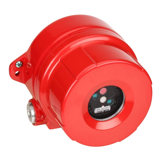
Page 27: Names And Description Of Parts
GTF-1100T Instruction Manual 7. Names and Description of Parts 7.1. Front Configuration [Figure 11: Front Configuration] Name Descriptions Green flickers when Normal Status LED Yellow flickers when Trouble Alarm LED Lights up during fire IR 1 Channel Sensor that detects wavelengths of 4.5~4.8 µm... -
Page 28: Parts
GTF-1100T Instruction Manual 7.2. Parts [Figure 12: Parts of GTF-1100T] PAGE 28 / 50 Rev 1.6(2024.06.10) - Page 29 GTF-1100T Instruction Manual Name Descriptions Protects sensors and PCB board installed in the housing from external Case body environment changes and impact. Put together with detector housing body, protects PCB board installed in the Case cover interior from external environment changes and impact.
-
Page 30: Dimensions
GTF-1100T Instruction Manual 8. Dimensions 8.1. GTF-1100T Dimensions [Figure 13: GTF-1100T Dimensions] PAGE 30 / 50 Rev 1.6(2024.06.10) -
Page 31: Gtf-1100T + Weather Proof Cover + Bracket Assembly Dimensions
GTF-1100T Instruction Manual 8.2. GTF-1100T + Weather Proof Cover + Bracket Assembly Dimensions [Figure 14: GTF-1100T + Weather Proof Cover + Bracket Assembly Dimensions] PAGE 31 / 50 Rev 1.6(2024.06.10) -
Page 32: Gtf-1100T Certification Label (Approval To Fm)
GTF-1100T Instruction Manual 8.1. GTF-1100T Certification Label (Approval to FM) [Figure 15: Certification Label (Approval to FM)] PAGE 32 / 50 Rev 1.6(2024.06.10) -
Page 33: Gtf-1100T Certification Label (Approval To Atex/Iecex/Nepsi)
GTF-1100T Instruction Manual 8.2. GTF-1100T Certification Label (Approval to ATEX/IECEx/NEPSI) [Figure 16: Certification Label (Approval to ATEX/IECEx/NEPSI)] PAGE 33 / 50 Rev 1.6(2024.06.10) -
Page 34: Operation
GTF-1100T Instruction Manual 9. Operation In order to prevent detector’s normal operation or damage, please energize after checking on wiring condition. 9.1. Energizing Energize after checking on wiring condition. When energized, Status LED and Alarm LED will flicker alternately and start Warm UP. -
Page 35: Test Using Fs-320 Simulator
GTF-1100T Instruction Manual 9.4. Test using FS-320 Simulator As the test using real fire in explosion-proof or hazard area was not available, replacement test using simulator was executed. Fire was detected from a source that creates spectrum similar with real fire by installed detector. -
Page 36: Approvals
GTF-1100T Instruction Manual 10. Approvals 10.1. CE Test Standard(method) Used: EN 50130-4:2011, EN61000-6-4:2007 + A1:2011 Emission Test Regulation / Standards Applied Standard Title EN 61000-6-4:2007 + A1:2011 Radiated Electric Filed Emissions [Table 21: Emission Test Regulation / Standards] ... -
Page 37: Atex/ Iecex/ Nepsi
GTF-1100T Instruction Manual 10.2. FM Approvals Classification Class I Division1 Groups A B C and D Class II, III Division1 Groups E F and G IP 66, 67 Explosion Proof type Explosion Proof Enclosure 10.3. ATEX/ IECEx/ NEPSI Approvals Classification ... -
Page 38: Accessories
11.1. Flame Simulator (Part No. FS-320) 11.1.1. Overview GTF-320 is a test simulator to identify GTF-1100T’s normal operation in explosion-proof or hazard area with the detector installed. This was produced to execute virtual fire test as test with real fire was unavailable. -
Page 39: General Specifications
GTF-1100T Instruction Manual 11.1.5. General Specifications I T E M S S P E C I F I C A T I O N Detection Distance Indicator Status LED (2 Color) Approvals Classification KCs: Ex dⅡB T4, T5, T6 Warranty 2Year 11.1.6. -
Page 40: Names Of Parts
GTF-1100T Instruction Manual Charger Input AC 100~240V / 50~60Hz / 1.0A Charger Output 16.8V / 2.5A Charger Indicator Bi-Color LED Indicator (RED & GREEN) Fully Charge Time App. 2 Hours [Table 24: FS-320 Specifications] 11.1.10. Names of Parts [Figure 17: Names of FS-320 Parts]... -
Page 41: Charging The Battery
GTF-1100T Instruction Manual Handle Handle that is designed for easy carriage of FS-320 Top Cover Part that engages to body to protect main board. Body Part that protects main board and battery pack. Back cover part that protects charger jack which connects to battery Back Cover pack. -
Page 42: Weather Proof Cover (Part No. Fwp-1000)
GTF-1100T Instruction Manual 11.2. Weather Proof Cover (Part No. FWP-1000) [Figure 18: Weather Proof Cover] 11.3. Weather Proof Cover Assembly PAGE 42 / 50 Rev 1.6(2024.06.10) - Page 43 GTF-1100T Instruction Manual GTF-1100T Cover Ring 1. Remove cover ring from GTF-1100T by turning as shown in the diagram. GTF-1100T Weather Proof Cover Cover Ring 2. Attach Weather Proof Cover to GTF-1100U first, then tighten cover ring. [Figure 19: Weather Proof Cover Assembly] PAGE 43 / 50 Rev 1.6(2024.06.10)
-
Page 44: Mounting Bracket Dimension (Part No. Fmb-1000)
GTF-1100T Instruction Manual 11.4. Mounting Bracket Dimension (Part No. FMB-1000) [Figure 20: Bracket Dimension] PAGE 44 / 50 Rev 1.6(2024.06.10) -
Page 45: Bracket Assembly
GTF-1100T Instruction Manual 11.5. Bracket Assembly Assemble using M6x12L bolts with bracket hole and Mount tap on GTF-1100T as shown in the diagram. M6x12L Bolt M4x6L Bolt (Weather Cover) Bracket GTF-1100T [Figure 21: Bracket Assembly] PAGE 45 / 50... -
Page 46: Bracket Tilt
GTF-1100T Instruction Manual 11.6. Bracket Tilt [Figure 22: Bracket Tilt] PAGE 46 / 50 Rev 1.6(2024.06.10) -
Page 47: Cable Grand Direction
GTF-1100T Instruction Manual 11.7. Cable Grand Direction Direction Figure Seen from the front of detector Right Seen from the front of detector Left [Table 28: Cable Grand] PAGE 47 / 50 Rev 1.6(2024.06.10) -
Page 48: Precautions During Installation
GTF-1100T Instruction Manual 12. Precautions during Installation When installing, places that can bring electrical harm (such as rain) should be avoided. As GTF-1100T requires periodic maintenance, it is also recommended to install in places where work can be done easily. -
Page 49: Warning
GTF-1100T Instruction Manual 13. Warning Use cables rated 20K greater than the maximum ambient temperature. The equipment includes flame path joints, consult with the manufacturer if repair of the flame path joints is necessary. Under certain extreme circumstances, exposed plastic (including powder coating) and unearthed metal parts of the enclosure may store an ignition-capable level of electrostatic charge. -
Page 50: Revision Records
GTF-1100T Instruction Manual 15. Revision Records Version Contents Date Initial Manual Revision Oct 22, 2018 Revised by Ex Marking Jan 21, 2019. Revised by another Ex Marking Jan 24, 2019 Revised by Correct Typos Jan 30, 2019 Revised by Ex Marking...
Need help?
Do you have a question about the GTF-1100T and is the answer not in the manual?
Questions and answers