Table of Contents
Advertisement
Advertisement
Table of Contents

Related Manuals for GASTRON GIR-3000


Summary of Contents for GASTRON GIR-3000
- Page 1 GIR-3000 Instruction Manual Read in detail for correct use.
- Page 2 GIR-3000 Instruction Manual Gas & Flame Detection System When abnormalities occur after purchasing the product, please contact the following address. ·Address : 23 Gunpo Advanced Industry 1-ro, Gunpo-si, Gyeonggi-do ·Tel : 031-490-0800 ·Fax : 031-490-0801 ·URL : www.gastron.com ·e-mail : info@gastron.com...
- Page 3 Gas detectors satisfying customers. From now on, solve all anguishes concerning Gas detector with the products of Gastron Co. Ltd, We Gastron Co. will take a responsibility and give you satisfaction. In the present instruction manual, operation method for Gas detector as well as simple methods for maintenance and repair, etc.
-
Page 4: Table Of Contents
GIR-3000 Contents Instruction Manual Overview · · · · · · · · · · · · · · · · · · · · · · · · · · · · · · · · · · · · · · · · · · · · · · · · · · · · · · · · · · · · · · · · · · · · · · · · · · · · · · · · · · · · · · · · · ·... - Page 5 · · · · · · · · · · · · · · · · · · · · · · · · · · · · · · · · · · · · · · · · · · · · · · · · · · · · · · · · · · · · · · · · 10.4. GIR-3000 Remote Type ·...
-
Page 6: Overview
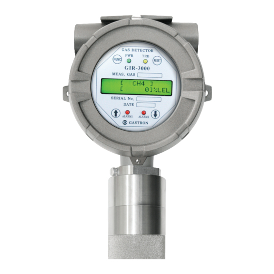
The GIR-3000 infrared Gas detector is installed in areas with a risk of gas leakage to display measured values with LCD, OLED installed in the detector by continuous detection of gas leakage, providing DC 4~20mA standard output, Isolation RS-485 communication signal, HART communication, and Relay contact signal of gas Alarm. -
Page 7: Specification
3. Specifications www.gastron.com 06_07 3.1. Basic Specifications ITEMS SPECIFICATION Measuring Type Diffusion type Measuring Value Display Local Digital LCD or OLED Display Measuring Method Non-Dispersive Infrared(NDIR) Combustible Gas Detectible Gas Carbon dioxide (CO2) Carbon monoxide(CO) Measuring Range 0~9,999ppm / 0~100% LEL /... -
Page 8: Electrical Specifications (Standard Type)
GIR-3000 3. Specifications Instruction Manual 3.3. Electrical Specifications (Standard Type) ITEMS SPECIFICATION Input Voltage(Standard) Absolute min: ※ Customer supplied PSU must meet Nominal: requirements IEC1010-1 and CE Absolute max: Marking requirements. Ripple maximum allowed: 1V pk-pk Max. wattage: 9.6W @+24 VDC Wattage Max. -
Page 9: Name And Description Of Each Part
4. Name and description of each part www.gastron.com 08_09 4.1. Components of transmitter [Figure 2. Components of GIR-3000] ITEMS SPECIFICATION Protect PCB Board embedded inside Sensor and Housing from change of Housing outside environments and impact. Amplify output signals produced by Sensor, and convert to standard output of DC 4~20mA for Main PCB transmission, and output Isolation RS- 485 communication Signal and Alarm relay contact signal. - Page 10 B. On the contrary, if in ENERGIZER MODE, it operates as contact B when Jumper is connected to A, while it operates as contact A when Jumper is connected to B. Warning Light Connecting connector when the warning light is used(Optional) Connector [Table 1. Description on components of GIR-3000 transmitter]...
-
Page 11: Components Of Infrared Sensor
4. Name and description of each part www.gastron.com 10_11 4.2. Components of infrared sensor ITEMS SPECIFICATION Power & Signal cable Comprised of power supply input, 4-20mA analog signal, and transmitter communication cable. Detector fixed screw Screw processing part for mounting of transmitter... - Page 12 GIR-3000 5. Installation Instruction Manual Absolutely no one other the approved users or those of the headquarters in charge of installation and repair should be allowed to install in the field, open or operate Cover of the installed gas leakage detector. Otherwise serious damages to life and property may be inflicted.
- Page 13 5. Installation www.gastron.com 12_13 5.2. Configuration of Main PCB ■ When Display Parts are separated, the layout diagram for Main PCB terminal as follows can be seen. [Figure 5.Layout diagram for Main PCB terminals] NAME DESCRIPTION CN12 Power & Output Signal Terminal...
- Page 14 GND / POWER (-) EARTH [Table 4. Detailed description on CN12 terminal] ■ Upon configuring the Terminal, use CVVS or CVVSB 2.0sq↑ Shield Cable. ■ To connect 4Pin Terminal of the existing old-style GIR-3000, fasten the terminal based on +24V as No.2 plate.
- Page 15 5.3.1. Wire connection diagram of driving method for 4~20mA Source ■ Connect 4-20mA Signal terminal on PLC side to GIR-3000의 'mA', while GND terminal is used in common with the power supply. And then turn the J1 Jumper ON. ■ HART Communicator can be used only in the model using HART Option board [Figure 7.Configuration of 4-20mA Source]...
- Page 16 4~20mA 3Wire Sink ■ Connect 4-20mA Sink output (+) terminal on PLC side to VISO terminal, and (-) terminal to (24V DC) (-) terminal. Connect 'mA' terminal of GIR-3000 to 'GND' terminal. Then connectturn the J1 Jumper OFF. [Figure 9. Configuration of 4-20mA 3Wire Sink] 5.4.
- Page 17 [Figure 11.Setting for Relay Mode] ■ For driving of Relay of GIR-3000 product, 2 types of Normal open and Normal close are operated. To allow setting of Main PCB에 Relay driving method, Jumper is configured with operation setting as follows.
- Page 18 GIR-3000 5. Installation Instruction Manual 5.5. Configuration of sensor-connecting terminal ■ IR sensor module (to be referred to as GSA920A hereafter) is connected to the transmitter by using CN No.10 terminal. [Figure 12. Sensor-connecting terminal] TER. NO. PIN NO. TERMINAL NAME...
- Page 19 5.6. Configuration of Remote Type connection ■ To remotely configure GSA920A, the sensor is installed by using Junction Box(GDH-1010) of the following form, and connection is made to GIR-3000 transmitter by using component terminal inside Junction Box. Wire connection Wire connection...
- Page 20 Instruction Manual 5.7. Length of installed cable ■ The maximum length between GIR-3000 and power supply is determined by the wire specifications. ■ Maximum installation length= VMAXDROP ÷ IMAX ÷ WIRER/m ÷ 2 ■ VMAXDROP: Maximum Power Loop Voltage Drop (=Power Supply voltage - min operating voltage) ■...
- Page 21 - When the power supply is turned ON , model name of LCD(OLED) is displayed in the 1st row, while GIR-3000 firmware version of the transmitter and firmware version of the sensor unit are displayed in the 2nd row.
- Page 22 ■ When "RESET" key is touched in program Mode screen, it is returned to measuring state, while it is returned to the upper stage when "RESET" key is touched in each program setting screen. [Figure 16. Configuration of GIR-3000 mode] ITEM...
- Page 23 6. Sensor operation Flow www.gastron.com 22_23 6.4. Menu Configuration Table LEVEL2 LEVEL1 DEFAULT NAME PARAMETER GROUP OF GAS SEL HC/PROPANE/CO/CO2/ (GROUP OF GAS SELECT) SO2/VCM/FREON UNIT & TAG SEL. %/%LEL/PPM/PPB %LEL (UNIT & TAG SELECT) PROGRAMMABLE MODE DECIMAL POINT 0.100/1.00/10.0/100 HIGH SCALE ADJ.
- Page 24 GIR-3000 6. Sensor operation Flow Instruction Manual 6.4. Menu Configuration Table LEVEL2 LEVEL1 DEFAULT NAME PARAMETER ALARM1 TIME SET [0~60] SEC ALARM2 TYPE SEL. INCREASE/ DECREASE INCREASE (ALARM2 TYPE SELECT) ALARM2 LEVEL ADJ [1~Full Scale] ALARM PROGRAM (ALARM2 LEVEL ADJUST)
- Page 25 7. System Mode www.gastron.com 24_25 7.1. PROGRAM MODE - Enter in the Level1 mode after Password checking. PROGRMAMMABLE - "Select PROGRAMMABLE MODE by touching "↑" key or "↓" key. MODE - When Function key is touched at this time, PROGRAMMABLE MODE Level2 serve menu is entered in.
- Page 26 GIR-3000 7. System Mode Instruction Manual 7.2. CALIBRATION MODE ■ Due to the characteristics of Gas detector, a stabilization time of at least about 30 minutes is required after supply of power, and the management criteria may be varied with field conditions..
- Page 27 7. System Mode www.gastron.com 26_27 7.2.2. Span Calibration SPAN CALIBRATION - Span Calibration Mode is entered in if FUNC key is touched when it is [YES] by touching "↑" key or "↓" key. [YES] - Span calibration is automatically executed if FUNC key is touched when the measured value is...
- Page 28 GIR-3000 7. System Mode Instruction Manual 7.3. ALARM MODE - Enter in Level1 mode after password checking. ALARM PROGRAM - Select ALARM MODE by touching "↑"key or "↓"key. MODE - ALARM MODE Level2 is entered in when Function key is touched at this time.
- Page 29 7. System Mode www.gastron.com 28_29 7.3. ALARM MODE - Mode for setting the direction for operation of Alarm2 with "INCREASE" or "DECREASE" displayed ALARM2 TYPE SEL. [INCREASE ] whenever "↑"key or "↓"key is touched. - "INCREASE" Mode is the mode operating when it is larger than or the same as the setting value for ALARM2 TYPE SEL.
- Page 30 GIR-3000 8. Troubleshooting Instruction Manual 8.1. Fault List FAULT MESSAGE DESCRIPTION & CONDITION CAUSE FOR OCCURRENCE FAULT0 When Memory(FLASH, RAM) Check Sum error Transmitter inside MPU defective "> TSM-MEM C/S" occurs inside the transmitter FAULT1 When EEPROM Check Sum error or EEPROM Transmitter inside EPROM defective ">...
- Page 31 8. Troubleshooting www.gastron.com 30_31 8.2. Recovery List CAUSE FOR OCCURRENCE COPING MEASURE MPU inside transmitter defective Replace Transmitter Main Board 1) Revise and recalibrate Parameter after execution of plant initialization EPROM inside transmitter defective 2) Replace Main Board when the same phenomenon occurs...
- Page 32 GIR-3000 9. Interface configuration Instruction Manual 9.1. MODBUS RS485 9.1.1. Interface setting ■ Data Format: RTU ■ Baud rate: 9600 bps ■ Data bits: 8bits ■ Stop bit: 1bits ■ Parity: Even ■ See www.modbus.org for other details 9.1.2. MODBUS RS485 Register map...
- Page 33 10. Outline drawing and Dimensions www.gastron.com 32_33 10.1. Standard Type [Figure 17. outline drawing for GIR-3000 Standard Type]...
- Page 34 GIR-3000 10. Outline drawing and Dimensions Instruction Manual 10.2. Upon coupling of warning light [Figure 18. Outline drawing for coupling of GIR-3000 warning light]...
- Page 35 10. Outline drawing and Dimensions www.gastron.com 34_35 10.3. Upon coupling of Raincover [Figure 18. Outline drawing for coupling ofGIR-3000 warning light]...
- Page 36 GIR-3000 10. Outline drawing and Dimensions Instruction Manual 10.4. GIR-3000 Remote Type [Figure 20. GIR-3000 remote Type]...
- Page 37 11. Notes before installation www.gastron.com 36_37 11.1. Selection of installation place (Data from occupational safety and health regulations The place to install the gas leakage detection alarm is as follows. ■ Surroundings of chemical equipment or accessory equipment with a risk of gas leakage such as compressor, valve, reactor, piping connection part, etc.
- Page 38 GIR-3000 11. Notes before installation Instruction Manual 11.3. Notes upon installation Positions with rainwater, etc. that can be an electrical obstacle should be avoided for installation, and installation at a place facilitating operation is recommended since periodic maintenance and repair is required. Since places with vibration or impact can affect output values, avoid those places with vibration or impact for installation, and install in such a way that the sensor unit is directed toward the direction of gravity.
- Page 39 * Correct typo for Fault Table and add content * Revision of apparatus-related drawing 2017.07.26 * Revision of block diagram for GIR-3000 * Revise TABLE OF CONTENTS so as to start from item 3P * Revise measurement range 10,000ppm → 9,999ppm * Revise No.4 item DC 18 ~ 24V →...
- Page 40 Headquarters / Engineering research laboratory : 23 Gunpo Advance d Industry 1-ro(Bugok-dong), Gunpo-si, Gyeonggi-do Tel +82-31-490-0800 Fax +82-31-490-0801 Yeongnam business office / Plant : 55 Gonghangap-gil 85beon-gil, Gangseogu, Busan Metropolitan City Tel +51-973-8518 Fax +51-973-8519 E-mail : info@gastron.com www.gastron.com...
Need help?
Do you have a question about the GIR-3000 and is the answer not in the manual?
Questions and answers