Table of Contents
Advertisement
Quick Links
Advertisement
Table of Contents

Related Manuals for SEPTENTRIO AsteRx-m2a


Summary of Contents for SEPTENTRIO AsteRx-m2a
- Page 1 AsteRx-m2a Product Group Hardware Manual Version 1.4.0...
- Page 2 AsteRx-m2a Product Group Hardware Manual Version 1.4.0 July 27, 2018 © Copyright 2000-2018 Septentrio nv/sa. All rights reserved. Septentrio Greenhill Campus, Interleuvenlaan 15i 3001 Leuven, Belgium http://www.septentrio.com support@septentrio.com Phone: +32 16 300 800 Fax: +32 16 221 640 @septentrio...
-
Page 3: Table Of Contents
1 Table of contents TABLE OF CONTENTS ....................3 ASTERX-M2A OEM ......................8 Mounting ........................9 Environmental ......................9 Power and Power Consumption ................9 RF Interface ......................10 2.4.1 Electrical Specifications .................... 10 2.4.2 System Noise Figure and C/N0 ................10 I/O Connectors ....................... - Page 4 Antenna Connectors ..................... 27 LEDs ......................... 28 COM Ports ....................... 28 3.10 PPS Out and Event Inputs ..................29 3.11 Ethernet ........................29 3.12 USB Dev ........................30 3.13 USB Host ......................... 30 3.14 REF IN ........................30 3.15 Buttons ........................30 3.16 SD Card Socket .......................
- Page 5 2002/95/EC on the restriction of the use of certain hazardous substances in electrical and electronic equipment (RoHS Directive). The AsteRx-m2a receiver complies with the European Union (EU) Directive 2002/96/EC on waste electrical and electronic equipment (WEEE). The purpose of this Directive is the prevention of waste electrical and electronic equipment (WEEE), and in addition, the reuse, recycling and other forms of recovery of such wastes so as to reduce the disposal of waste.
- Page 6 Statement 0001/WARNING: The power supply provided by Septentrio (if any) should not be replaced by another. If you are using the receiver with your own power supply, it must have a double isolated construction and must match the specifications of the provided power supply.
- Page 7 Electronic components and assemblies, such as Septentrio OEM receivers, can be permanently damaged or destroyed when near or in contact with electro-statically charged objects. When you handle components or assemblies that are not in protective bags and you are not sure whether they are static-sensitive, assume that they are static-sensitive and handle them accordingly.
-
Page 8: Asterx-M2A Oem
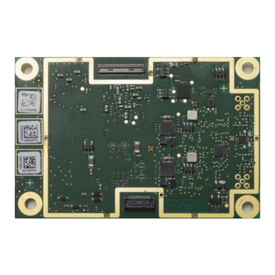
AsteRx-m2a OEM 2 AsteRx-m2a OEM Pin#1 view from above, I/O connectors on the bottom side Pin#1 All dimensions in millimeters. Weight = 28 g RF connectors (u.FL type) are mounted on top side of the PCB. The 30- and 60-pin Hirose... -
Page 9: Mounting
AsteRx-m2a OEM 2.1 Mounting The four mounting holes are compatible with M3 screws. Use M3 3.5mm spacers. An example of applicable SMD spacer is THF-1.6-3.5-M3 from MAC8. All mounting holes are grounded, and should preferably be connected to ground on the host PCB. -
Page 10: Rf Interface
AsteRx-m2a OEM 2.4 RF Interface The main antenna must be connected to the ANTA u.FL and the auxiliary antenna must be connected to the ANTB u.FL connector. 2.4.1 Electrical Specifications Antenna supply voltage 3-5.5V DC, set via pin#18 of the 30-pin connector ANTA u.FL connector: DC always applied... - Page 11 AsteRx-m2a OEM NFrx is the receiver noise figure, in dB. NFrx depends on the net gain, but a good • approximation (<0.5dB) of NFsys can be obtained by setting NFrx = 10dB. Gpreamp is the net gain in front of the receiver, in dB.
-
Page 12: I/O Connectors
AsteRx-m2a OEM 2.5 I/O Connectors 60 pin 30 pin The main connector is the 30-pin connector. That connector must always be connected. The 60-pin connector provides additional signals (IO enable, serial CTS/RTS lines, GPIOs, Ethernet, 10-MHz reference input, etc). That connector can be ignored and left unconnected if these signals are not needed. -
Page 13: 30-Pin Connector
AsteRx-m2a OEM 2.5.1 30-pin Connector Connector type: Hirose 30 pins DF40HC (3.5)-30DS-0.4V(51) Mating connector: Hirose DF40C-30DP-0.4V(51) See the pin numbering convention in the above picture. Pin# Name Type Level Description Comment 3.3V Main power supply input Both Vin pins (pin#1 and pin#2) must +/-5% be tied together. -
Page 14: 60-Pin Connector
Serial COM2 RTS line. The AsteRx-m2a drives this pin low when ready to receive data. RTS3 LVTTL Serial COM3 RTS line. The AsteRx-m2a drives this pin low when ready to receive data. LVTTL Serial COM 4 transmit line (inactive state is high) - Page 15 Reserved CTS2 I, K LVTTL Serial COM 2 CTS line. Must be driven low when ready to receive data from the AsteRx-m2a. CTS3 I, K LVTTL Serial COM 3 CTS line. Must be driven low when ready to receive data from the AsteRx-m2a.
-
Page 16: External Frequency Reference Input (Ref In)
2V and 5V, for example it can be an LVTTL clock signal. At start-up, the AsteRx-m2a checks the presence of the external frequency reference on pin#60. If a signal is present, the receiver uses that signal as primary frequency reference, instead of its internal TCXO. -
Page 17: Sd Memory Card Usage
AsteRx-m2a OEM It is also possible to schedule automatic standby/wakeup periods using the setWakeUpInterval command. Note that entering standby mode takes a few seconds during which all running processes are shutdown. 2.10 SD Memory Card Usage The receiver can interface to an external SD memory card through the SD-card pins of the 30-pin connector. -
Page 18: Usb Interface
AsteRx-m2a OEM 2. By driving the button pin (pin#25) low for at least 5 seconds before turning off the receiver. 2.11 USB Interface The user can configure the USB device interface in either USB 1.1 (full speed) mode, or in USB 2.0 (high speed) mode. - Page 19 AsteRx-m2a OEM...
-
Page 20: Asterx-M2A Uas
AsteRx-m2a UAS 3 AsteRx-m2a UAS The AsteRx-m2a UAS consists of an AsteRx-m2a receiver board mounted on an interface card specifically designed to ease integration in UAS (Unmanned Aerial Systems) and mobile mapping applications. This chapter provides information on the interface card only. Refer to chapter 2 for the... -
Page 21: Connectors
.1" RA Header 1x2 3.3V-LVTTL event input. Connects to the This header can be connected to the flash EventA pin of the AsteRx-m2a through an port of a camera (e.g. via Hot Shoe or inverter. A high-to-low transition at the J7... -
Page 22: Power Supply Options
AsteRx-m2a UAS Note that the 60-pin connector of the AsteRx-m2a is not used by the interface card. Refer to the board schematics in section 3.5 and to the picture on page 20 for the pinout of each connector. 3.2 Power Supply Options When an USB cable is connected, the interface board is powered from the computer through the USB connector (J2). - Page 23 The interface board connects the SD-card DAT3 pin to pin#24 of the 30-pin connector of the AsteRx-m2a. This connection is there to make the interface board compatible with the legacy AsteRx-m receiver. New designs made for the AsteRx-m2a should leave the SD-card DAT3 pin unconnected.
- Page 24 AsteRx-m2a UAS See note above...
- Page 25 AsteRx-m2a UAS...
-
Page 26: Development Kit
USB Dev USB Host 3&4 REF IN The AsteRx-m2a Development Kit is specifically designed to simplify the development process for new integrations. 3.6 Powering the DevKit There are two ways to power the DevKit: 1. From the USB Dev connector (J205). This allows powering the board from a PC or from a standard phone-charger adapter. -
Page 27: Antenna Connectors
Development Kit To measure the power consumption of the AsteRx-m2a OEM board (excluding the contribution from the DevKit and the antenna), remove the jumper on J200 and connect the two pins to the probes of a multimeter in current-sensing mode. Measure the current flowing between the two pins and multiply it by 3.3V to obtain the power consumption. -
Page 28: Leds
COM 2 COM 4 By default, the four COM ports of the AsteRx-m2a are routed to the four DB9 connectors. Electrical levels on the BD9 conform to the RS232 standard. RTS/CTS lines are supported only on COM2 and COM3. Connection to a PC is done through a null-modem cable. -
Page 29: Pps Out And Event Inputs
EVENTB EVENTA The PPSout pin of header J500 is directly connected to the PPSOut pin of the AsteRx-m2a (see section 2.5.1). The PPS level is 3.3V. The EVENTA and EVENTB pins of J500 are connected to the EventA and EventB pins of the AsteRx-m2a through a buffer. -
Page 30: Usb Dev
3.15 Buttons nRST LOGGING Pressing the nRST button drives the nRST pin of the AsteRx-m2a low, which resets the receiver. Pressing the LOGGING button drives the Button pin of the AsteRx-m2a low. This can be used to enabled and disable logging, as described in section 2.10. -
Page 31: Appendix Aled Status Indicators
LED Status Indicators Appendix A LED Status Indicators The LED pins can be used to monitor the receiver status. They can be used to drive external LEDs (max drive current 10mA). It is assumed that the LED lights when the electrical level of the corresponding pin is high. - Page 32 LED Status Indicators The LOGLED reports the SD card mount status and logging activity. LED Behaviour LOGLED LED is off when the SD card is not present or not mounted. LED is on when the SD card is present and mounted. Short blinks indicate logging activity.
-
Page 33: Appendix Bemc Considerations
This is where the RF spectrum monitor built in the AsteRx-m2a comes in handy. The spectrum monitor can be accessed in RxControl under the View / Spectrum View menu. The spectrum can also be monitored offline if the BBSamples SBF blocks are logged. - Page 34 EMC Considerations An example of interference is shown below. This particular interference at about 1598 MHz falls in the GLONASS L1 band and slightly degrades the L1 C/N0 of some GLONASS satellites. Try to keep personal computers and other equipment more than 2 meters away from the antenna while assessing electromagnetic compatibility of the integration.
- Page 35 (see the setNotchFiltering command). Intermittent wide-band cross-talk can often be eliminated with the wide band interference canceller (see the setWBIMitigation command). AsteRx-m2a has been designed to minimize radiation and can be used close to an antenna without additional shielding.
Need help?
Do you have a question about the AsteRx-m2a and is the answer not in the manual?
Questions and answers