Table of Contents
Advertisement
Quick Links
Original Instructions
INSTRUCTION MANUAL
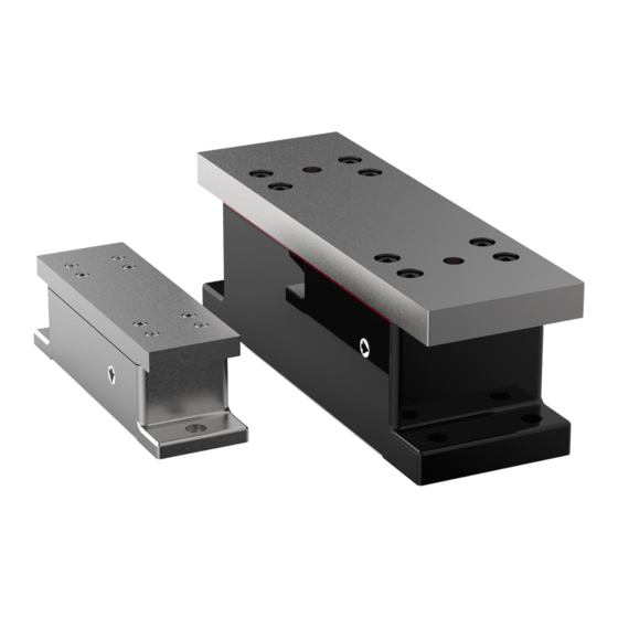
Model GTS
Load Cells For Under Pillow Block Applications
All of the information herein is the exclusive proprietary property of Maxcess International, and is disclosed with the
understanding that it will be retained in confidence and will neither be duplicated nor copied in whole or in part nor be
used for any purpose other than for which disclosed.
Copyright 2011, all rights reserved.
Periodically there will be updates to this manual. The latest version is available at
www.magpowr.com
or by calling 1-800-
MAGPOWR (624-7697).
These load cell devices must not be installed or used in a machine or system which does not comply with the machinery
directive 2006/42/EC.
These load cell devices were designed and manufactured to be installed as Partly Completed Machinery into a machine
or partly completed machine.
The instructions must be read and used by all persons who have the responsibility of installing and maintaining these load
cell devices.
These instructions must be retained and incorporated in the technical documentation for the machine or partly completed
machinery into which the load cell device was installed.
CE MARKING
Only the 2006/42/EC Machinery directive applies to these devices and they are not marked with the CE sign.
Electromagnetic Compatibility (EMC)
The load cell device is inherently benign in terms of electromagnetic compatibility and the EMC directive has not been
applied. The electromagnetic compatibility of the load cell device can only be assessed in connection with the entire
electrical installation including the control. The machine builder who installs this partly completed machinery into a
machine is responsible for compliance with the EMC directive.
INTRODUCTION
The model GTS load cell is designed to be mounted under standard inch and metric pillow block bearings. All GTS load
cells are pre-drilled and tapped to accept standard inch and metric pillow block bearings. Top Plate Adapter kits are also
available to accommodate special mounting requirements for the metric series of GTS load cells. GTS load cells are
compatible with all MAGPOWR tension readouts and controls.
THEORY OF OPERATION
The load cell construction consists of a beam with a metal foil strain gage bonded at the bending point of the beam. The
spring constant of the beam causes the beam to deflect with the applied force. The beam deflection causes the strain in
the metal below the strain gage to vary linearly with the applied force. The strain gage converts the induced strain into an
electrical signal which is proportional to the induced strain.
1
850A193-1
01/11 Rev.E
Advertisement
Table of Contents

Subscribe to Our Youtube Channel
Related Manuals for Maxcess GTS


Summary of Contents for Maxcess GTS
- Page 1 INTRODUCTION The model GTS load cell is designed to be mounted under standard inch and metric pillow block bearings. All GTS load cells are pre-drilled and tapped to accept standard inch and metric pillow block bearings. Top Plate Adapter kits are also available to accommodate special mounting requirements for the metric series of GTS load cells.
- Page 2 MODEL NUMBER KEY Series – Size – Maximum Force – UnitsType – Sxx Series: GTS – Global Tension Sensor Size: A, B Maximum Force: Pounds = English Models Kilograms = Metric Models UnitsType: Blank = English units (dimensions and force)
- Page 3 MECHANICAL AND ELECTRICAL INSTALLATION CAUTION – Possible damage to load cell. Do not hammer on the GTS load cell. CAUTION – Possible damage to load cell. Do not disassemble the load cell – There is nothing inside that you can repair.
- Page 4 2. GTS load cells are designed to be mounted under standard, self-aligning pillow block bearings, which support an idler roll shaft. Two GTS load cells should be used to measure tension on one idler roll. Mount the load cells on opposite sides of the machine, on a clean and flat surface of the machine frame.
- Page 5 DIMENSIONS INCH MODEL DIMENSIONS (INCHES) Model GTSA 7.25 6.375 3.750 1.00 2.00 2.50 0.422 3/8-16 0.63 0.50 GTSB 11.19 10.000 6.250 1.25 2.50 3.88 0.500 7/16-14 1.00 1.00 METRIC MODEL DIMENSIONS (MILLIMETERS) Model GTSAM M10X1.5 GTSBM M12X1.75 TOP PLATE ADAPTERS...
- Page 6 SPECIFICATIONS WARNING – Do not use the devices outside of their rated specifications. Gage Resistance 350 ohm Gage Type Metal foil, full bridge Excitation Voltage 10 VDC nominal Output Signal 21 mVDC nominal at full load rating Operating Temperature -30ºC to 95ºC Temperature effect on zero 0.02% of rating per ºC Combined non-linearity and hysteresis...
- Page 7 Degrees Sine Cosine Degrees Sine Cosine 0.0000 1.0000 0.7660 0.6428 To properly size any model GTS load cell select the case (which 0.0872 0.9962 0.8192 0.5736 resembles your application) from the examples shown below. 0.1736 0.9848 0.8660 0.5000 Using your known maximum tension, roll weight, and angles as 0.2588...
- Page 8 To request service or to get replacement parts, contact one of the following addresses: Fife Corporation Fife-Tidland GmbH 222 West Memorial Rd. Fifestrasse 1 Siemensstrasse 13-15 Oklahoma City, OK, 73114, USA 65779 Kelkheim 48683 Ahaus Phone: 1-405-755-1600 Deutschland Deutschland Fax: 1-405-755-8425 Telefon: +49-6195-7002-0 Web: www.maxcessintl.com Fax: +49-6195-7002-933 Web: www.maxcess.eu...
Need help?
Do you have a question about the GTS and is the answer not in the manual?
Questions and answers