Hachette U-BOAT U96 Assembly Instructions Manual
Hide thumbs
Also See for U-BOAT U96:
- Assembly instructions manual (21 pages) ,
- Assembly instructions manual (19 pages) ,
- Assembly instructions manual (14 pages)

Related Manuals for Hachette U-BOAT U96


Summary of Contents for Hachette U-BOAT U96
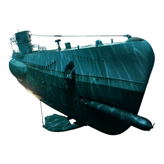
- Page 1 U 96 Pack 12 Kits 45-48 25 20 U-BOAT BUILD THE ICONIC WORLD WAR II U-BOAT...
- Page 2 Kit 45: The next motor Kit 46: Limit switches Kit 47: Another motor Kit 48: The hull © 2023/2024 Hachette Partworks Ltd. ALL RIGHTS RESERVED Not suitable for children under 14. Hachette Partworks Ltd WARNING: All parts belong to a kit.
- Page 3 Kit 45: The next motor In this kit, the motor for raising and lowering the attack periscope is fitted with a cable and attached to the periscope rack. 45-2 45-1 45-3 45-4 Parts reference list Part no. Name 45-1 Motor Screws 45-2 45-3...
- Page 4 Kit 45: The next motor STAGE 1 Attaching the motor Remove the wrapper from the cable 45-3 and the backing film from the cable label 45-4, as shown. 45-3 45-4 Attach the label 45-4 to the cable 45-3 approximately 8mm from the larger connector.
- Page 5 Kit 45: The next motor Fit the cog 45-2 onto the hub of the motor 45-1. Take the attack periscope 44-2 assembly 44-1/44-2 and fit the cog and motor into the mounting on the rack as indicated by the arrows. 45-1 45-2 44-1...
- Page 6 Kit 46: Limit switches In this kit, limit switches are fitted to the central periscope. The periscope assembly is then installed and equipped with a cover, cog and bracket. 46-1 46-2 46-3 46-5 46-4 46-6 Parts reference list Part no. Name 46-1 Shaft cover...
- Page 7 Kit 46: Limit switches STAGE 1 Attaching the limit switches and assembling the shaft 46-6 46-6 44-1 44-1 Place the periscope assembly, limit switch 46-6 and a screw Attach the limit switch with the black cable 46-6 to the rack cover ready on your work surface.
- Page 8 Kit 46: Limit switches 46-5 46-1/46-2 46-5 46-1/46-2 Now fit the cog 46-5 onto the end of the shaft cover assembly Slide the gear 46-5 down the shaft cover 46-1/46-2 until it sits 46-1/46-2, as shown in the inset photo and in the next step. Note against the bead.
- Page 9 Kit 46: Limit switches Take the shaft cover assembly 46-1/46-2, oriented as pictured, and fit it onto the periscope 44-4, as indicated by the arrow. If necessary, rotate the shaft cover so that if fully engages below. 44-4 46-1/46-2 This photo shows the shaft 46-1/46-2 correctly fitted around the periscope 44-4.
- Page 10 Kit 46: Limit switches Take the motor bracket cover 46-4 and fit it against the other half 46-3. 46-4 46-3 Fasten the two halves of the motor bracket cover 46-3 46-4 using two screws, as shown. 46-4 46-3 COMPLETED WORK The periscope assembly, with limit switches in place, has been installed in the central...
- Page 11 Kit 47: Another motor In this kit, the motor for rotating the attack periscope is fitted with a cable and then attached to the top of the periscope mount. 47-1 47-2 47-3 47-4 Parts reference list Part no. Name 47-1 Screws 47-2 Motor...
- Page 12 Kit 47: Another motor STAGE 1 Attaching the motor Take the cable label 47-4 and cable 47-3 remove the wrapping, as shown. 47-4 47-3 Peel the cable label 47-4 from its backing film and attach it approximately 8mm from the larger connector on cable 47-3. Taking the motor 47-2, connect the end of the 47-3 cable without the label to the socket on...
- Page 13 Kit 47: Another motor Place the cog 47-1 and motor 47-2 onto the mounts on the attack periscope bracket 46-3. 47-2 47-1 46-3 Fix the motor 47-2 to the bracket 46-3 using two screws. 46-3 47-2 COMPLETED WORK The motor for rotating the attack periscope has now been fitted to the central compartment assembly.
- Page 14 Kit 48: The hull In this kit, the next section of the lower hull is attached to the structure using a connector, then the second and third compartments are inserted and fixed within the hull assembly. 48-1 48-2 Screws Parts reference list Dimensions Part no.
- Page 15 Kit 48: The hull STAGE 1 Attaching the hull section and adding the compartments 30-1 48-2 48-2 30-1 Orientate the connector 48-2 as pictured above and fit it against Fix the connector 48-2 to the lower hull section 30-1 using the four the aft end of the lower hull section 30-1, as indicated by the arrow.
- Page 16 Kit 48: The hull Insert the assembly consisting of compartments 2 and 3 into the hull structure: the forward bulkhead of the second compartment 27-1 should sit up against the bow compartment bulkhead 20-1. The aft bulkhead 37-1 of the third compartment fits into a recess in the connector 48-2.
Need help?
Do you have a question about the U-BOAT U96 and is the answer not in the manual?
Questions and answers