
Related Manuals for Biobase BSC-4FA2-HA


Summary of Contents for Biobase BSC-4FA2-HA
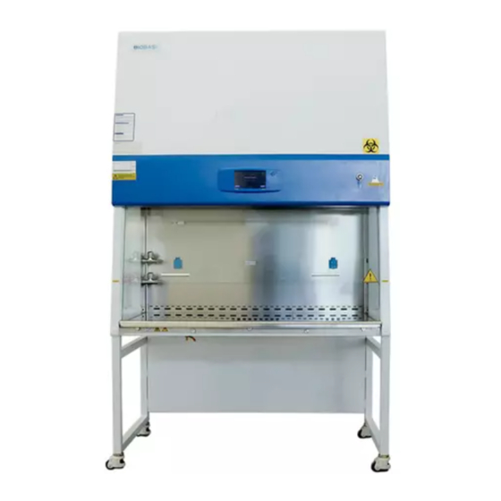
- Page 1 Microbiological Safety Cabinet BSC-4FA2-HA User Manual BIOBASE GROUP Version 2021.09...
-
Page 3: Preface
Preface Thank you very much for purchasing our class II A2 Microbiological Safety Cabinet. Please read the “1. Precaution” and “4.4 Instructions for Operation” before operating this unit to assure proper operation. After reading these documents, be sure to store them securely together with the “Warranty”... -
Page 4: Table Of Contents
4.1.3 Working theory/Air flow pattern and protected area............ 15 4.1.4 Protected objects......................15 4.1.5 Technical parameters.....................16 4.1.6 Performance Index......................16 4.2 Product structure........................17 4.2.1 Structural composition of BSC-4FA2-HA..............17 4.2.2 Structure introduction....................17 4.3 Control panel........................... 20 4.3.1 Touch screen display window..................20 4.3.2 Buttons...........................21 4.4. - Page 5 4.5.3 Overall maintenance period...................23 4.5.4 Maintenance methods....................23 4.6 Methods and procedures for disinfection................24 4.7 Replacement parts list......................27 4.8 Wiring diagram........................28 5. Trouble shooting and Labels......................29 5.1 Common faults & solution...................... 29 5.1.1 Warning and reminder....................29 5.1.2 Trouble shooting......................29 5.1.3 Simple accessories replacement..................
-
Page 6: Precautions
1. Precautions Under all conditions marked with , it is necessary to consult the document, so as to clarity the nature of potential risks and any countermeasures that must be taken. Actions or operations which are prohibited. Actions or operations which must be followed Make sure input voltage is correct and stable. - Page 7 ULPA filter life: With the usage time increasing, dust and bacteria accumulate inside ULPA filter. Filter Resistance is getting bigger, when it reaches the maximum point, there will be audible and visual alarm. Please replace new ULPA filter, otherwise it will affect the safety performance of the equipment.
- Page 8 face. There is risk to move the parts moving. Relevant personnel can use this equipment must after training. while the front window must be raised to 200mm and in this case person can operate in the cabinet. In this way we can reduce harm out of front window trouble. When the equipment is repaired or scrapped.
-
Page 9: Warranty
2.Warranty 1) Warranty is 12 months from EX-factory date (excluding consumable accessories and Fluorescent lamp, fuse). 2) We will take no responsibility for risks caused by improper operation and man-made damages. 3) After the expiration of warranty, our company is also responsible for repairs, but the corresponding maintenance cost should be charged. -
Page 10: Unpacking, Installation, Debugging
3. Unpacking, Installation, Debugging Please firstly check if packing box is in good condition. If the packing box is damaged, please take photos. 3.1 Unpacking Choose the proper unpacking method according to the actual situation. For wooden box: 1) Method 1 Use M8 Wrench to unpack Picture 1... - Page 11 2) Method 1 Necessary tools for unpacking: Electric drill with hexagon dead M8 Picture2 Rapid unpacking diagram (Picture 3). Disassemble the screws shown in the below Picture, then move the wooden pieces to right and left. Picture 3...
-
Page 12: Accessories Checking
3.2 Accessories checking Refer to the packing list and check the accessories. BSC-4FA2-HA Packing List Items Model Position Quantity Main Body Wooden box 1 set Base Stand Placed in two carton box 1 set UV Lamp (T6 30W) Top or back of main body 1 pc Protective fuse(12.5A,250V) -
Page 13: Installation
placing the cabinet, it should avoid restricting its exhaust.Biological safety cabinets should be in the direction of the air flow downstream and the side of the security cabinet at least 300mm space to help check. Working environment: (1) Only is suitable for indoor use; (2) Altitude not exceeding 2000m;... - Page 14 Right bracket The bolts in the red ring shall not be removed M10 * 20 hexagon socket Left bracket head cap screw Picture 4 Remove the M10×20 Hexagon socket head screws, Buckle plug, M10 Stainless steel flat washer, M10 Stainless steel spring washer, M10 Stainless steel cap nuts, referring to Picture 5 assembled base, firmly fastening requirements.
- Page 15 Take out the M10*20 Hexagon socket head screws, Flat washer 10, Spring washer 10 from the accessory box, and fasten tightly according to Picture 6. M10*20 Hexagon socket head bolt + flat washer 10 + spring washer 10 ,through the base, connect with the M10 welded nut on the bottom...
-
Page 16: Checking After Installation
Picture8 1. Drain valve connecter 2. Shim (Inner diameter*outer diameter*thicknessΦ20*Φ28*2mm) 3. Safety cabinet bottom installation holes 4. Ball coupling fastening nut 5. Rubber gasket (Inner diameter*outer diameter*thicknessΦ13*Φ19*2mm) 6. Drain valve Take out drain valve coupling, shim(Inner diameter*outer diameter*thicknessΦ20*Φ28*2mm), Ball nut, Rubber gasket(Inner diameter*outer diameter*thicknessΦ13*Φ19*2mm), Drain valve, assembling from up to down as Picture 8 illustrated. -
Page 17: User Instructions
4. User Instructions 4.1 Functions 4.1.1 Product Concept This cabinet defined as class II A2 type Microbiological Safety Cabinet, It totally meets the European standard for biological cabinet EN 12469:2000 standard. Microbiological Safety Cabinet is a kind of negative pressure filtration system for protecting operator, the laboratory environment and work materials, the front opening which air flow inward have protection function for operator, the filtered laminar flow generated by vertical ULPA can protect work materials, what’s more, the polluted air flow become pure after processed by ULPA filter. -
Page 18: Technical Parameters
4.1.5 Technical parameters Model BSC-4FA2-HA Parameters Power Supply (230V±10%);50Hz External 1383*800*2260(mm) Size(W*D*H) Working Zone 1280*600*650(mm) Size(W*D*H) Rated power 1200 W Total Airflow 490 m Volume Downflow Velocity 0.33 m/s Inflow Velocity 0.53 m/s Fluorescent lamp 14W*2 Consumption UV Lamp Consumption ULPA Filter 99.9995%(Diameter:0.12μm)... -
Page 19: Product Structure
Reinforced insulation: between live parts and non-metallic shell in the AC voltage 3000V, continuous 1min without breakdown. Leakage current ≤10mA. Grounding resistance ≤0.1Ω 4.2 Product structure 4.2.1 Structural composition of BSC-4FA2-HA Fuma caster Alarm rest plate Air intake grid Door glass... - Page 20 the down flow velocity, and keep Class 10 cleanness of work area. 3) UV Light UV lamp is inside work area. So UV lamp can well sterilize all space of work area. Emission of 253.7 nanometers can ensure most efficient decontamination. 4) LED lamps light source LED lamps are used for lighting to ensure that the average illumination in the operation area meets the standard requirements.
- Page 21 Capacitive touch screen works by the current induction of human body. Capacitive touch screen is a four-layer composite glass screen. The inner surface and interlayer of the glass screen are coated with a layer of ITO, respectively, and the outer layer is a thin layer of silica glass protective layer. The interlayer ITO coating is used as the working face, four electrodes are led out from four corners, and the inner layer ITO is the shielding layer to ensure a good working environment.
-
Page 22: Control Panel
10) Warnings and reminders Digital differential pressure display, digital wind speed display, audible and visual alarm system. a)Alarm for glass door exceeding safety height When the front glass door is too high, it will give an audible and visual alarm, and the alarm will flash on the touch screen. -
Page 23: Buttons
4.3.2 Buttons Password interface: after power on, the password interface will pop up. The initial password is 2222, and the password can be modified. The modification method is shown below. Button function: After pressing the corresponding function button, there will be icon display on the display screen and the corresponding function will be started. -
Page 24: Instructions For Operation
password modification interface. Enter the original password to enter the modification interface to modify the user password and click “confirm” button to exit. Glass door up button: press the up button continuously, the glass door will continue to rise, and stop when it is 200 mm away from the worktable, continue to press the up button until the lowest point of travel is reached, and release the button, the glass door will stop moving. -
Page 25: Clean The Cabinet Surface
4.5.2 Clean the cabinet surface 1) Clean the operating area surface Wipe the entire surface with a soft cotton cloth or towel soaked with concentrated liquid soap, then wipe up the soap with another cotton cloth or towel soaked with clean hot or warm water, and then wipe the surface with a dry cotton cloth or towel rapidly. -
Page 26: Methods And Procedures For Disinfection
of operating area) and the inner surface of glass door with 70﹪ medical alcohol. c. Check the various functions of equipment; d. Record this maintenance result; 3) Annual maintenance a. Check the two conveyor belts of front window drive unit and ensure that their tightness is coincident. - Page 27 neutralization reaction. Ammonium hydrogen carbonate need to be more than 10% to ensure the complete reaction. c、If there is exhaust pipe in safety cabinet, the pipeline must be airtight. The terminal air tightness in the pipe can be realized, or if there is a valve regulating valve closed in the safe cabinet near. If the exhaust pipe is longer than 3m, please increase the amount of paraformaldehyde in order to compensate for the increased volume.
- Page 28 Occupational Safety and Health Administration guidelines on occupational exposure to formaldehyde in claim airborne formaldehyde concentrations exceed permissible exposure limits area should be prescribed as a control area, marked out with signs and symbols of the region, only appropriately trained personnel. We must review and observe current regulations; m、...
-
Page 29: Replacement Parts List
4.7 Replacement parts list BSC-4FA2-HA Replacement parts list Designation Parameter Lamp holder T8 GZ10 UV Lamp QT-FIT 5/8 1x18-39 LED Lamp PAK410110 UV lamp ballast QT-FIT 5/8 1x18-39 Upper filter (Exhaust filter) 800*430*69(mm) Downflow filter (Supply filter) 1240*500*69(mm) DH230A2-AG5-05 LCD control board (strong circuit... -
Page 30: Wiring Diagram
4.8 Wiring diagram BSC-4FA2-HA Wiring diagram... -
Page 31: Trouble Shooting And Labels
5. Trouble shooting and Labels 5.1 Common faults & solution 5.1.1 Warning and reminder Digital display of pressure difference, digital velocity display, audible and visual alarm system. 1) Over safety height alarm for front window There will be audio and visual alarm when front window is lifting over safety height. Same time LCD display will twinkle exclamation mark. -
Page 32: Simple Accessories Replacement
Blower If blower is broken, change it Circuit Check circuit Control panel Change it No electricity in Socket Check if socket is broken socket Socket fuse Check if socket fuse is broken Circuit Check circuit Control panel Change it Pressure or air Gas circuit Check whether gas circuit has dropped, is broken, speed displayed... - Page 33 Support bar Take out one tip of support bar behind Remove the two hole plugs Hole plugs the control panel to from the left and right mount on the cabinet sides,Use screwdriver to loose the screws Picture 14 2)Replace the UV lamp UV lamp should be replaced regularly according to the frequency of use, when using UV lamps reach to the time of 1000 hours, we recommend to replace the lamp.
- Page 34 lamp, it needs to keep pressing the button of UV for about five seconds when the machine stays standby. Picture 15 3)Replace the fuse Power plug fuse is located on the power supply board, when replace it, turn off the power and disconnect plug, take out of the fuse and replace with a new fuse, and then press it back.
-
Page 35: Label Description
5.2 Label Description Biological hazard label Ground label(Protected Ground Earthing) Safe operation glass door height Filter scan label Sewage valve label, sewage valve biological hazard label, warning label Waterproof socket power total capacity Warning:Electrical Shock Attention Use warning labels... - Page 36 Operation area warning label Operation area label Label of air tap Faucet label Precautions for glass lifting Front window warning film UV lamp warning label Electrical warning label...
- Page 37 Marking of left internal wiring Marking of right internal wiring Hole plugs Support rod Remove label Use instruction label for support rod The switch warning label...
-
Page 38: Emc
6.EMC 1) The device meets the emission and immunity requirements of EN 61326:2013. 2) The device is tested according to classA. Biosafety cabinets need to take special precautions in terms of electromagnetic compatibility (EMC), and must be installed and used according to the EMC information provided in this manual. Perform-ance Port Phenomenon... - Page 39 BIOBASE GROUP 2# building, No.9 Gangxing Road, High-tech Zone, Jinan City, Shandong Province, China Tel: +86-531-81219803/01 Fax: +86-531-81219804 Inquiry: export@biobase.com Complaints: customer_support@biobase.cc After-sales service: service_sd@biobase.cc; service_ivd@biobase.cc Web: www.biobase.cc/www.meihuatrade.com / www.biobase.com...
Need help?
Do you have a question about the BSC-4FA2-HA and is the answer not in the manual?
Questions and answers