Sign In
Upload
Download
Table of Contents
Contents
Add to my manuals
Delete from my manuals
Share
URL of this page:
HTML Link:
Bookmark this page
Add
Manual will be automatically added to "My Manuals"
Print this page
×
Bookmark added
×
Added to my manuals
Manuals
Brands
Biobase Manuals
Laboratory Equipment
BBS-H1300
User manual
Biobase BBS-H1300 User Manual
Horizontal laminar flow cabinet
Hide thumbs
1
2
Table Of Contents
3
4
5
6
7
8
9
10
11
12
13
14
15
16
17
18
19
20
21
22
23
24
25
26
27
28
page
of
28
Go
/
28
Contents
Table of Contents
Troubleshooting
Bookmarks
Table of Contents
Preface
Table of Contents
Content
Unpacking, Installation and Debugging
Unpacking
Accessories Checking
Installation Conditions and Operating Environment
Installation
Checking after Installation
User Instructions
Functions
Product Concept
Operating Principle/Air Flow Pattern
Protected Objects
Technical Parameters
Product Structure
Structural Composition of BBS-H1300/BBS-H1800
Instructions of Operation
Normal Operation Notice
Operation Process
Daily Maintenance
Clean the Cabinet Surface
Clean the External Surface and Front Window
Overall Maintenance Period
Maintenance Methods
Storage Conditions
Replacement Parts List
Wiring Diagram (Picture 12)
Trouble Shooting and Solution
Common Failures and Solutions
Replace the Fuse
Replace LED Lamp
Replace the UV Lamp
Label Description (Picture 15)
Warranty
Advertisement
Quick Links
1
Preface
2
Table of Contents
3
Unpacking, Installation and Debugging
4
User Instructions
5
Technical Parameters
6
Instructions of Operation
Download this manual
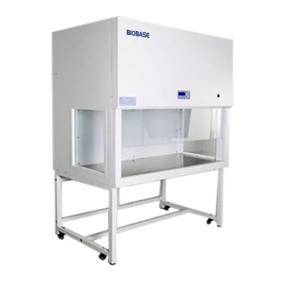
Horizontal Laminar Flow Cabinet
BBS-H1300/H1800
User Manual
BIOBASE GROUP
Version 2021.12
Table of
Contents
Previous
Page
Next
Page
1
2
3
4
5
Advertisement
Table of Contents
Need help?
Do you have a question about the BBS-H1300 and is the answer not in the manual?
Ask a question
Questions and answers
Related Manuals for Biobase BBS-H1300
Laboratory Equipment Biobase BBS-V800 User Manual
Vertical laminar flow cabinet (21 pages)
Laboratory Equipment Biobase BBS-V1300 User Manual
Vertical laminar flow cabinet (27 pages)
Laboratory Equipment Biobase BBS-V1800 User Manual
Vertical laminar flow cabinet (27 pages)
Laboratory Equipment Biobase BBS-DDC User Manual
Vertical laminar flow cabinet (30 pages)
Laboratory Equipment Biobase BBS-SDC User Manual
Vertical laminar flow cabinet (30 pages)
Laboratory Equipment Biobase BBS-DSC User Manual
Vertical laminar flow cabinet (30 pages)
Laboratory Equipment Biobase BBS-SSC User Manual
Vertical laminar flow cabinet (30 pages)
Laboratory Equipment Biobase BBS-H1800 User Manual
Horizontal laminar flow cabinet (28 pages)
Laboratory Equipment Biobase BSC-4FA2-GL User Manual
(33 pages)
Laboratory Equipment Biobase BSC-4FA2-HA User Manual
(39 pages)
Laboratory Equipment Biobase BSC-3FA2-NA User Manual
(32 pages)
Laboratory Equipment Biobase BSC-2FA2-HA User Manual
(39 pages)
Laboratory Equipment Biobase BK-AutoHS96 User Manual
(55 pages)
Laboratory Equipment Biobase BK-HS32 User Manual
Automatic nucleic acid extraction system (29 pages)
Laboratory Equipment Biobase BKQ-B Series Maintenance Manual
Vertical autoclave sterilizer (21 pages)
Laboratory Equipment Biobase BKMZB User Manual
Table-top autoclave (39 pages)
This manual is also suitable for:
Bbs-h1800
Table of Contents
Save PDF
Print
Rename the bookmark
Delete bookmark?
Delete from my manuals?
Login
Sign In
OR
Sign in with Facebook
Sign in with Google
Upload manual
Upload from disk
Upload from URL


Need help?
Do you have a question about the BBS-H1300 and is the answer not in the manual?
Questions and answers