
Subscribe to Our Youtube Channel
Related Manuals for probst AKZ-UNI-H


Summary of Contents for probst AKZ-UNI-H
- Page 1 Betriebsanleitung Operating Instructions Instructions d'emploi AKZ-UNI-H 56100101 DE/GB/FR...
- Page 5 Betriebsanleitung Original Betriebsanleitung Aufbaukranzange AKZ-UNI-H AKZ-UNI-H 56100101...
- Page 6 Bitte beachten Sie, dass das Produkt ohne vorliegende Betriebsanleitung in Landessprache nicht eingesetzt / in Betrieb gesetzt werden darf. Sollten Sie mit der Lieferung des Produkts keine Betriebsanleitung in Ihrer Landessprache erhalten haben, kontaktieren Sie uns bitte. In Länder der EU / EFTA senden wir Ihnen diese kostenlos nach.
-
Page 7: Table Of Contents
Reparaturen ..............................24 Prüfungspflicht ............................. 25 Hinweis zum Typenschild ..........................26 Hinweis zur Vermietung/Verleihung von PROBST-Geräten ................ 26 Entsorgung / Recycling von Geräten und Maschinen ..................26 Schmieranweisung (Parallel-Gleitführungen) ..................... 27 Änderungen gegenüber den Angaben und Abbildungen in der Betriebsanleitung sind vorbehalten. -
Page 8: Eg-Konformitätserklärung
DIN EN ISO 13857 Sicherheit von Maschinen - Sicherheitsabstände gegen das Erreichen von Gefährdungsbereichen mit den oberen und unteren Gliedmaßen Dokumentationsbevollmächtigter: Name: Jean Holderied Anschrift: Probst GmbH; Gottlieb-Daimler-Straße 6; 71729 Erdmannhausen, Germany Unterschrift, Angaben zum Unterzeichner: Erdmannhausen, 26.04.2022................(Eric Wilhelm, Geschäftsführer) 56100101... -
Page 9: Sicherheit
Sicherheit Sicherheit Sicherheitshinweise Lebensgefahr! Bezeichnet eine Gefahr. Wenn sie nicht gemieden wird, sind Tod und schwerste Verletzungen die Folge. Gefährliche Situation! Bezeichnet eine gefährliche Situation. Wenn sie nicht gemieden wird, können Verletzungen oder Sachschäden die Folge sein. Verbot! Bezeichnet ein Verbot. Wenn es nicht eingehalten wird, sind Tod und schwerste Verletzungen, oder Sachschäden die Folge. -
Page 10: Sicherheitskennzeichnung
Sicherheit Sicherheitskennzeichnung VERBOTSZEICHEN Symbol Bedeutung Bestell-Nr. Größe 29040210 Ø 30 mm Niemals unter schwebende Last treten. Lebensgefahr! 29040209 Ø 50 mm 29040204 Ø 80 mm 29040213 Ø 30 mm Es dürfen keine konischen Greifgüter gegriffen werden. 29040212 Ø 50 mm 29040211 Ø... -
Page 11: Persönliche Sicherheitsmaßnahmen
Sicherheit BEDIENUNGSHINWEISE Symbol Bedeutung Bestell-Nr. Größe Minimaler Arbeitsdruck am Trägergerät: 180 bar 29040820 85 x 30 mm Maximaler Arbeitsdruck am Trägergerät: 210 bar Persönliche Sicherheitsmaßnahmen • Jeder Bediener muss die Bedienungsanleitung für das Gerät mit den Sicherheitsvorschriften gelesen und verstanden haben. •... -
Page 12: Funktions- Und Sichtprüfung
Sicherheit Funktions- und Sichtprüfung 2.8.1 Mechanik • Das Gerät muss vor jedem Arbeitseinsatz auf Funktion und Zustand geprüft werden. • Wartung, Schmierung und Störungsbeseitigung dürfen nur bei stillgelegtem Gerät erfolgen! • Bei Mängeln, die die Sicherheit betreffen, darf das Gerät erst nach einer kompletten Mängelbeseitigung wieder eingesetzt werden. -
Page 13: Sicherheit Im Betrieb
Sicherheit Sicherheit im Betrieb 2.9.1 Allgemeines • Die Arbeit mit dem Gerät darf nur in bodennahem Bereich erfolgen. Das Schwenken des Gerätes über Personen hinweg ist untersagt. • Der Aufenthalt unter schwebender Last ist verboten. Lebensgefahr! • Das manuelle Führen ist nur bei Geräten mit Handgriffen erlaubt. •... -
Page 14: Hebezeuge/Lkw-Aufbaukrane
Sicherheit 2.9.2 Hebezeuge/LKW-Aufbaukrane • Der Bediener des Hebezeuges muss die gesetzlich vorgeschriebenen Qualifikationen erfüllen. • Nur beauftragte und qualifizierte Personen dürfen das Hebezeug / den LKW-Aufbaukran bedienen. • Das eingesetzte Hebezeug inklusive Tragmittel muss sich in betriebssicherem Zustand befinden. • Die maximal erlaubte Traglast des Hebezeugs darf unter keinen Umständen überschritten werden! 2.9.3 Sicherheit im Hydraulikbetrieb... -
Page 15: Allgemeines
Allgemeines Allgemeines Bestimmungsgemäßer Einsatz Die Aufbaukranzange AKZ ist speziell für den strapaziösen Einsatz am Ladekran eines LKW konzipiert worden. Das Gerät dient ausschließlich zum Be- und Entladen von gebündelten, palettierten oder unpalettierten Greifgütern, wie Steinstapel, Pflastersteine und sonstigen Baustoffen. Vertikal, scheibenweise umreifte Baustoffpakete und Produkte ab einer Bauhöhe von 200 mm (auch unumreift) dürfen gegriffen und angehoben werden. - Page 16 Allgemeines • Das Gerät darf nur für den in der Bedienungsanleitung beschriebenen bestimmungsgemäßen Einsatz, unter Einhaltung der gültigen Sicherheitsvorschriften und unter Einhaltung der dementsprechenden gesetzlichen Bestimmungen und den der Konformitätserklärung verwendet werden. • Jeder anderweitige Einsatz gilt als nicht bestimmungsgemäß und ist verboten! •...
-
Page 17: Übersicht Und Aufbau
5. Optionale Schraubhaken (für Seile oder Gurte) 6. Greifbacken Seitenteile, teleskopisch verstellbar zur Einstellung der Eintauchtiefe (Et) Technische Daten Zangenkörperlänge Öffnungsweite Eintauchtiefe Tragfähigkeit* (WLL) Eigengewicht [mm] [mm] [kg] [mm] [kg] AKZ-UNI-H 370 – 1.370 1.100 – 1.650 1.900 56100101 12 / 27... - Page 18 Allgemeines Die Tragfähigkeit (WLL) ist abhängig von: • Oberflächenbeschaffenheit des Greifgutes • Größe der einzelnen Steine • Paketgröße • Art der Verpackung Für Stapel aus niedrigen, ungebündelten Steinen, z.B. Pflastersteinen, gelten die Tragfähigkeiten (WLL) nicht! Beim Einhängen von Lasten an den optionalen Schraubhaken (mit Seilen, Gurten oder Ketten), darf die Tragfähigkeit (WLL) von Schraubhaken für Seile,...
-
Page 19: Installation
Installation Installation Mechanischer Anbau Nur Original-Probst-Zubehör verwenden, im Zweifelsfall Rücksprache mit dem Hersteller halten. Die Tragfähigkeit des Trägergerätes/Hebezeuges darf durch die Last des Gerätes, der optionalen Anbaugeräte (Drehmotor, Einstecktasche, Kranausleger etc.) und die zusätzliche Last der Greifgüter nicht überschritten werden! Greifgeräte müssen immer kardanisch aufgehängt werden, so dass sie in jeder Position frei auspendeln... -
Page 20: Einstecktaschen (Optional)
Einstecktasche Seil oder Kette Montage der optionalen Schraubhaken (optional) 4.1.3 Beim Einsatz der optionalen Schraubhaken (5) an der AKZ-UNI-H müssen IMMER alle 4 Schraubhaken montiert werden. 85 Nm Um ein sicheres Arbeiten zu gewährleisten, müssen jeweils die 2 Befestigungsschrauben der... -
Page 21: Hydraulischer Anbau
Installation Hydraulischer Anbau • Zum Betrieb des Gerätes (AKZ) und des Drehmotors sind zwei getrennte hydraulische Steuerkreise erforderlich. • Verfügt der LKW-Ladekran nur über einen Steuerkreis, kann durch den Einbau eines elektromagnetischen Umschaltventils (ELMV) dieser eine Steuerkreis in zwei aufgeteilt werden. •... -
Page 22: Einstellungen
Einstellungen Einstellungen Vorsicht bei Einstellungsarbeiten! Verletzungsgefahr der Hände! Schutzhandschuhe verwenden. Die Eintauchtiefe (E) darf nicht am hängenden Gerät vorgenommen werden! Seitenteile können unkontrolliert herunterfallen! Verletzungsgefahr! Abb. 1 Abb. 2 56100101 17 / 27... - Page 23 Einstellungen Zum Verstellen der Eintauchtiefe E (Abb. 2) muss das Gerät sicher auf dem Boden stehen! Das senkrechte Mittelrohr ist mit vier Bohrungen versehen, die sich auf unterschiedlichen Höhenniveaus befinden und jeweils um 90° versetzt sind. • Federriegel um 180° nach oben bewegen und arretieren - somit ist das Mittelrohr frei drehbar.
-
Page 24: Bedienung
Bedienung Bedienung • Die Funktionen „Öffnen“ und „Schließen“ werden durch die am LKW-Ladekran angebrachten Ventilsteuerhebel betätigt. • Die Funktionen „Öffnen“ und „Schließen“ erfolgen, solange die Ventilsteuerhebel betätigt werden. • Das Drehen der Aufbaukranzange mit dem Drehmotor darf nur sehr behutsam erfolgen, da die Ladung ansonsten herausgeschleudert werden kann. - Page 25 Bedienung Die dargestellten Arbeitsbewegungen dürfen mit dem Gerät keinesfalls ausgeführt werden! Bruchgefahr des Gerätes und Drehkopfes! Abrutschgefahr des Greifgutes! Bei Nichtbeachtung besteht höchste Unfall- sowie Lebensgefahr! 56100101 20 / 27...
- Page 26 Bedienung 56100101 21 / 27...
-
Page 27: Wartung Und Pflege
Wartung und Pflege Wartung und Pflege Wartung Um eine einwandfreie Funktion, Betriebssicherheit und Lebensdauer des Gerätes zu gewährleisten, sind die in der Tabelle aufgeführten Wartungsarbeiten nach Ablauf der angegebenen Fristen durchzuführen. Es dürfen nur Original-Ersatzteile verwendet werden, ansonsten erlischt die Gewährleistung. Alle Arbeiten dürfen nur im drucklosen, stromlosen und beim stillgelegten Zustand des Gerätes erfolgen! Bei allen Arbeiten muss sichergestellt sein, dass sich das Gerät nicht unbeabsichtigt schließen kann. -
Page 28: Hydraulik
Wartung und Pflege 7.1.2 Hydraulik WARTUNGSFRIST Auszuführende Arbeiten • Erstinspektion nach Sämtliche Hydraulikverschraubungen kontrollieren bzw. nachziehen 25 Betriebsstunden (darf nur von einem Sachkundigen durchgeführt werden). • Erstinspektion nach Hydraulikflüssigkeit austauschen (empfohlenes Hydrauliköl: HLP 46 nach DIN 51524 – 50 Betriebsstunden 51535). -
Page 29: Störungsbeseitigung
Wartung und Pflege Störungsbeseitigung STÖRUNG URSACHE BEHEBUNG Die Klemmkraft ist nicht ausreichend, die Last rutscht ab. (optional) Die Greifbacken sind abgenutzt Greifbacken erneuern (optional) Traglast ist größer als zulässig Traglast reduzieren Öffnungsweiten-Einstellung Es ist die falsche Öffnungsweite Öffnungsweite entsprechend der zu (optional) eingestellt transportierenden Güter einstellen. -
Page 30: Prüfungspflicht
• Die dementsprechenden gesetzlichen Bestimmungen u. die der Konformitätserklärung sind zu beachten! • Die Durchführung der Sachkundigenprüfung kann auch durch den Hersteller Probst GmbH erfolgen. Kontaktieren Sie uns unter: service@probst-handling.de • Wir empfehlen, nach durchgeführter Prüfung und Mängelbeseitigung des Gerätes die Prüfplakette „Sachkundigenprüfung / Expert inspection“... -
Page 31: Hinweis Zum Typenschild
(z.B. Kran, Kettenzug, Gabelstapler, Bagger...) mit zu berücksichtigen. Beispiel: Hinweis zur Vermietung/Verleihung von PROBST-Geräten Bei jeder Verleihung/Vermietung von PROBST-Geräten muss unbedingt die dazu gehörige Original- Betriebsanleitung mitgeliefert werden (bei Abweichung der Sprache des jeweiligen Benutzerlandes, ist zusätzlich die jeweilige Übersetzung der Original-Betriebsanleitung mit zuliefern)! Entsorgung / Recycling von Geräten und Maschinen... -
Page 32: Schmieranweisung (Parallel-Gleitführungen)
Entsorgung / Recycling von Geräten und Maschinen Schmieranweisung (Parallel-Gleitführungen) Art.-Nr.: 60200015 56100101 27 / 27... - Page 33 (durch eine autorisierte Fachwerkstatt)! Nach jeder erfolgten Durchführung eines Wartungsintervalls muss unverzüglich dieser Wartungsnachweis (mit Unterschrift u. Stempel) an uns übermittelt werden 1). 1) per E-Mail an: service@probst-handling.de / per Fax oder Post Betreiber: _ _ _ _ _ _ _ _ _ _ _ _ _ _ _ _ _ Gerätetyp:...
- Page 37 Operating Instructions Translation of original operating instructions Block Loading Grab AKZ-UNI-H AKZ-UNI-H 56100101...
- Page 38 Repairs ................................24 Safety procedures ............................25 Hints to the type plate ..........................25 Hints to the renting/leasing of PROBST devices ..................26 Disposal / recycling of devices and machines ....................26 Lubrication instructions (parallel-slide bearing guides) ................27 We hereby reserve the right to make changes to the information and illustrations in the operating instructions.
-
Page 39: Ec-Declaration Of Conformity / Ukca-Declaration Of Conformity
Address: Probst GmbH; Gottlieb-Daimler-Straße 6; 71729 Erdmannhausen, Germany Authorized person for UK-documentation: Name: Nigel Hughes Address: Probst Ltd ; Unit 2 Fletcher House; Stafford Park 17; Telford Shropshire TF3 3DG, United Kingdom Signature, information to the subscriber: Erdmannhausen, 23.05.2022................(Eric Wilhelm, Managing director) -
Page 40: Safety
Safety Safety Safety symbols Danger to life! Identifies imminent hazard. If you do not avoid the hazard, death or severe injury will result. Hazardous situation! Identifies a potentially hazardous situation. If you do not avoid the situation, injury or damage to property can result. -
Page 41: Safety Marking
Safety Safety Marking PROHIBITION SIGN Symbol Meaning Order-No. Size 29040210 Ø 30 mm It is not allowed to stand under hanging loads. Danger to life! 29040209 Ø 50 mm 29040204 Ø 80 mm 29040213 Ø30 mm The transportation of non-rectangular goods is not allowed! 29040212 Ø50 mm 29040211... -
Page 42: Personal Safety Requirements
Safety OPTIONAL Be sure that the fork sleeves are mechanically fixed (with locking 29040223 Ø 50 mm screw and safety chain or rope) to the lifting device. 29040222 Ø 80 mm OPERATING INFORMATIONS Symbol Meaning Order-No. Size Minimum working pressure at the carrier device: 180 bar 290400820 85 x 30 mm Maximum working pressure at the carrier device: 210 bar... -
Page 43: Function Control
Safety Function Control 2.8.1 General • Before every usage of the device check the functions and the working condition. • Maintenance and lubrication are only permitted when device is shut down! • Do not use the device, until all faults which can cause safety hazards are removed. •... - Page 44 Safety Safety procedures 2.9.1 General • The use of the device is only permitted in proximity to the ground. Do not swing it over people heads. • The stay under lifted load is forbidden. Danger to Life! • The manual guiding of the device is only allowed at the handles. •...
-
Page 45: Safety In Hydraulic Pressure Mode
Safety 2.9.2 Lifting devices / Truck loading cranes • The lifting device / truck loading crane including truss must be in good, safe working condition. • Only authorized and qualified persons are allowed to operate the lifting devices / truck loading cranes. •... -
Page 46: General
General General Authorized use The Block Loading Grab AKZ was designed particularly for the use with truck loading cranes. The device exclusively suitable for the loading and unloading of packed and unpacked, palleted und unpalleted gripping goods, like paving stones and other building materials. ... - Page 47 General • The device is only designed for the use specified in this documentation. • Every other use is not authorized and is forbidden! • All relevant safety regulations, corresponding legal regulations, especially regulations of the declaration of conformity, and additional local health and safety regulations must be observed. Prior to every operation the user must ensure that: •...
-
Page 48: Survey And Construction
Gripper Base Lenght Dead Weight (WLL) 370 – 1.370 mm 1.100 – 1.650 mm 1.900 kg 720 mm 422 kg AKZ-UNI-H (14 ½ - 54 ") (39 ¼ - 65 ") (4,200 lbs) (28 ¼ ") (928 lbs) 56100101 12 / 27... - Page 49 General The working load limit (WLL) depends on: • Surface condition of the material to be gripped • Size of the individual stones • Package size • Type of packaging The working load limit (WLL) do not apply to stacks of low, unbundled stones, e.g. paving stones! When hanging loads on the optional screw hooks (with ropes, Screw hook for belts or chains), the working load limit (WLL) of 750 kg (1,650 lbs)
-
Page 50: Installation
Installation Installation Mechanical connection Use only original accessories, in case of doubt consult the manufacturer. Take care that the carrying capacity / working load limit (WLL) of the lifting device/carrier is not exceeded, through the load of the device, the optional attaching devices (turning device, fork sleeves, crane boom etc.) and the additional load of the gripping goods! Gripping devices always have to be gimballed, so they can swing freely in any position. -
Page 51: Standard Flange Plate
Mounting the optional screw hooks (optional) 85 Nm When using the optional screw hooks (5) on the AKZ-UNI-H, ALWAYS mount all 4 screw hooks. To ensure safe working, the 2 fastening screws of the screw hooks must each be tightened with a... -
Page 52: Hydraulical Connection
Installation Hydraulical connection • To use the device (AKZ) two separate hydraulic circuits are required. • If the truck loading crane has only one control circuit, this one control circuit can be divided into two by installing an electromagnetic switching valve (ELMV). •... -
Page 53: Adjustments
Adjustments Adjustments Caution while adjustment work. There is danger of injuring the hands! Use safety gloves! → The inside height must not be carried out on the hanging unit! Side parts may fall down uncontrolled! Risk of injury! Fig. 1 Fig. - Page 54 Adjustments To adjust the inside height E (Fig. 2), the unit must stand securely on the ground! The vertical central tube is provided with four bores, which are located at different height levels and are each offset by 90°. • Move the spring bolt upwards by 180°...
-
Page 55: Operation
Operation Operation • The "open" and "close" functions are actuated by the valve control levers attached to the truck loading crane. • The "open" and "close" functions are performed as long as the valve control levers are actuated • The turning of the flange clamp with the turning motor must be carried out very carefully, otherwise the load may be ejected •... - Page 56 Operation Under no conditions may the machine be used to carry out the work movements shown! Danger of breakage of the implement and turning head! Danger of slipping of the material to be gripped! Failure to observe this warning may result in serious injury or death.
- Page 57 Operation 56100101 21 / 27...
-
Page 58: Maintenance And Care
Maintenance and care Maintenance and care Maintenance To ensure the correct function, safety and service life of the device the following points must be executed in the maintenance interval. Used only original spare parts, otherwise the warranty expires. All operations may only be made in unpressurised, electro less and closed state of the device! For all operations you have to make sure, that the device will not close unintended. -
Page 59: Hydraulic
Maintenance and care 7.1.2 Hydraulic Service interval Maintenance work First inspection after • Control and tighten all hydraulic thread joints and connection. 25 operating hours (The implementation is only allowed by an expert). All 50 operating hours • Tighten all hydraulic connections. •... -
Page 60: Trouble Shooting
Maintenance and care Trouble shooting ERROR CAUSE REPAIR The clamping-power is not big enough, the load is slipping out (optional) The grippers are worn Replace the grippers (optional) The maximum load is exceed Reduce the weight of. the load (Adjustment of the opening width) The actual opening width is not correct Adjust the opening width according to (optional) the load you want to transport... -
Page 61: Safety Procedures
• The corresponding legal regulations and the regulations of the declaration of conformity must be observed! • The expert inspection can also be done by the manufacturer Probst GmbH. Contact us at: service@probst-handling.de • We recommend affixing the inspection sticker "„Sachkundigenprüfung / Expert inspection" in a clearly visible place (order no.: 2904.0056+Tüv sticker with year number) after the inspection has been done. -
Page 62: Hints To The Renting/Leasing Of Probst Devices
Disposal / recycling of devices and machines Hints to the renting/leasing of PROBST devices With every renting/leasing of PROBST devices the original operating instructions must be included unconditionally (in deviation of the user´s country's language, the respective translations of the original... -
Page 63: Lubrication Instructions (Parallel-Slide Bearing Guides)
Disposal / recycling of devices and machines Lubrication instructions (parallel-slide bearing guides) Art.-Nr.: 60200015 56100101 27 / 27... - Page 64 After each completed performance of a maintenance interval the included form must be fill out, stamped, signed and send back to us immediately 1) via e-mail to service@probst-handling.de / via fax or post Operator: _ _ _ _ _ _ _ _ _ _ _ _ _ _ _ _ _...
- Page 65 Instructions d'emploi Traduction des instructions d'emploi originales Pince hydraulique pour grue de camion AKZ-UNI-H AKZ-UNI-H 56100101...
- Page 66 Réparations ..............................24 Devoir de contrôle ............................25 Informations concernant la plaque signalétique ..................25 Remarque concernant la location/le prêt des engins PROBST ..............26 Elimination / recyclage des appareils et des machines ..................26 Instructions de lubrification (glissières parallèles) ..................27 Nous nous réservons le droit de modifier les informations et les illustrations du mode d'emploi.
-
Page 67: Ce-Déclaration De Conformité
CE-Déclaration de Conformité CE-Déclaration de Conformité Description: Pince hydraulique pour grue de camion AKZ-UNI-H Type: AKZ-UNI-H N° de commande: 56100101 Fabricant: Probst GmbH Gottlieb-Daimler-Straße 6 71729 Erdmannhausen, Germany info@probst-handling.de www.probst-handling.com La machine décrite ci-dessus est conforme aux exigences applicables des directives UE suivantes : Idée directrice EC 2006/42/CE... -
Page 68: Sécurité
Sécurité Sécurité Instructions de sécurité Danger mortel ! Indique un danger. Si elle n'est pas évitée, elle peut entraîner la mort et des blessures graves. Situation dangereuse ! Indique une situation dangereuse. Le fait de ne pas l'éviter peut entraîner des blessures ou des dommages matériels. -
Page 69: Définition Du Personnel Qualifié / Expert
Sécurité Définition du personnel qualifié / expert Les travaux d'installation, d'entretien et de réparation sur cet appareil ne doivent être effectués que par du personnel qualifié ou des experts ! • Le personnel qualifié ou les experts doivent posséder les connaissances pour les mécaniciens professionnelles nécessaires dans les domaines suivants, dans la mesure où... -
Page 70: Mesures De Sécurité Personnelle
Sécurité OPTIONELLES Utiliser des vis de blocage et cordage ou chaîne pour sécuriser les 29040223 Ø50 mm fourreaux et les fourches du chariot élévateur. 29040222 Ø80 mm INSTRUCTIONS DE FONCTIONNEMENT Symbole Signification Réf. Taille Pression de service minimale sur le chariot : 180 bar 2904.0820 85 x 30 mm Pression de service maximale sur le chariot : 210 bar... -
Page 71: Essai De Fonctionnement Et Inspection Visuelle
Sécurité Essai de fonctionnement et inspection visuelle 2.8.1 Généralités • Le fonctionnement et l'état de l'appareil doivent être vérifiés avant chaque utilisation. • N’effectuez l‘entretien, le graissage et la remise en état de l’engin que lorsque celui-ci est à l’arrêt ! •... -
Page 72: Sécurité En Cours De Fonctionnement
Sécurité Sécurité en cours de fonctionnement 2.9.1 Généralités • Les travaux avec l'appareil ne doivent être effectués que dans une zone proche du sol. Il est interdit de balancer l'appareil sur des personnes. • Il est interdit de rester sous une charge suspendue. Danger pour la vie ! •... -
Page 73: Sécurité Du Système Hydraulique
Sécurité 2.9.3 Sécurité du système hydraulique • La force de maintien ou de serrage optimale est uniquement garantie si le levier de commande de l’appareil porteur est maintenu pendant deux secondes en position de fermeture après la fermeture de l’engin (opération de prise de la marchandise). Ensuite, le levier de commande doit à nouveau être ramené... -
Page 74: Généralités
Généralités Généralités Utilisation conforme La benne de camion AKZ a été spécialement conçue pour une utilisation intensive sur la grue de chargement d'un camion. L'appareil est utilisé exclusivement pour le chargement et le déchargement de grappins empaquetés, palettisés ou non ... - Page 75 Généralités Les surfaces de préhension des éléments en pierre doivent impérativement être parallèles et planes ! Risque de chute dans le cas contraire ! • L’appareil ne peut être utilisé que pour l’usage prévu dans la notice d’instructions, en respectant les règles de sécurité...
-
Page 76: Vue D´ensemble Et Structure
Panneaux latéraux, réglables de manière télescopique pour le réglage de la profondeur d'immersion Caractéristiques techniques Type Largeur d’ouverture Profondeur Charge admissible * Longueur corp de Poids propre bridage principale d’insertion (WLL) la pince AKZ-UNI-H 370 – 1.370 mm 1.100 – 1.650 mm 1.900 kg 720 mm 422 kg 56100101 12 / 27... - Page 77 Généralités La charge admissible (WLL) dépend de : • État de surface du matériau à saisir • Taille des pierres individuelles • Taille des colis • Type d'emballage Les charges admissibles (WLL) ne s'appliquent pas aux piles de pierres basses et dégroupées, comme par exemple les pavés ! Lors de l'accrochage de charges aux crochets à...
-
Page 78: Installation
Installation Montage sur l’appareil porteur N’utiliser que des accessoires Probst d’origine, en cas de doute prendre contact avec le fabricant. La charge admissible de l’appareil porteur /engin de levage ne doit pas être dépassée par la charge de l’appareil et des appareils rapportés (moteur vireur, poches à emboîter, potence etc.) ainsi que par la charge supplémentaire des objets à... -
Page 79: Plaque D'assemblage
4.1.3 Montage des crochets à vis (en option) Lors de l'utilisation des crochets à visser optionnels (5) sur l'AKZ-UNI-H, il faut TOUJOURS monter les 4 85 Nm crochets à visser. Afin de garantir un travail en toute sécurité, les 2 vis de fixation des crochets à... -
Page 80: Montage Hydraulique En Annexe À Une Unité De Base
Installation Montage hydraulique en annexe à une unité de base • Deux circuits hydrauliques de commande distincts sont nécessaires pour faire fonctionner l'unité (AKZ) et le moteur couple. • Si la grue de chargement de camion ne possède qu'un seul circuit de commande, celui-ci peut être divisé en deux en installant une vanne de commutation électromagnétique (ELMV). -
Page 81: Réglage
Réglage Réglage Soyez prudent lorsque vous effectuez des réglages. Risque de blessures aux mains. Porter des gants de protection. → La profondeur d'insertion (E) ne doit pas être effectuée sur l'appareil suspendu ! Les parties latérales peuvent tomber de manière incontrôlée ! Risque de blessure ! Fig. - Page 82 Réglage Pour régler la profondeur d'insertion E (Fig. 2), l'appareil doit reposer solidement sur le sol! Le tube central vertical est pourvu de quatre trous, situés à des hauteurs différentes et décalés chacun de 90°. • Déplacez le boulon à ressort de 180° vers le haut et verrouillez-le. Cela permet au tube central de tourner librement.
-
Page 83: Maniement
Maniement Maniement • Les fonctions "ouverture" et "fermeture" sont actionnées par les leviers de commande des soupapes fixés sur la grue de chargement du camion. • Les fonctions "ouverture" et "fermeture" sont exécutées tant que les leviers de commande de la vanne sont actionnés. - Page 84 Maniement Les mouvements de travail indiqués ne doivent en aucun cas être effectués avec l'appareil ! Risque de rupture de l'appareil et de la tête rotative ! Danger de glissement du matériel de préhension ! En cas d'inobservation, le risque d'accident et de danger de mort est élevé...
- Page 85 Maniement 56100101 21 / 27...
-
Page 86: Maintenance Et Entretien
Maintenance et entretien Maintenance et entretien Maintenance Pour que l´appareil fonctionne parfaitement, pour assurer sa sécurité de fonctionnement et une longue durée de vie, il est impératif d’effectuer les opérations de maintenance spécifiées dans le tableau ci-dessous aux intervalles prescrits. Utiliser exclusivement des pièces de rechange d’origine ;... -
Page 87: Hydraulique
Maintenance et entretien 7.1.2 Hydraulique DÉLAI DE MAINTENANCE Travaux à réaliser • Inspection initiale après Vérifiez ou resserrez tous les raccords hydrauliques à vis 25 heures de (ne peut être effectuée que par une personne qualifiée). fonctionnement • Inspection initiale après Remplacer le liquide hydraulique (huile hydraulique recommandée : HLP 46 selon DIN 50 heures de 51524 - 51535). -
Page 88: Élimination Des Dérangements
Maintenance et entretien Élimination des dérangements DÉPANNAGE CAUSE REMEDE La force de serrage n'est pas suffisante, la charge glisse. (facultatif) Les mâchoires des pinces sont usées Renouveler les mâchoires des pinces (facultatif) La capacité de charge est supérieure à ce Réduire la charge qui est autorisé... -
Page 89: Devoir De Contrôle
• Observer les prescriptions correspondantes des associations professionnelles déclaration de conformité. • Le contrôle expert peut également être effectué par le fabricant Probst GmbH. Contactez-nous à : service@probst-handling.de • Lorsqu’un contrôle a été effectué et que les déficiences ont été réparées sur l´appareil, nous conseillons d’apposer la plaquette „CONTRÔLE DE SÉCURITÉ“... -
Page 90: Remarque Concernant La Location/Le Prêt Des Engins Probst
Elimination / recyclage des appareils et des machines Remarque concernant la location/le prêt des engins PROBST Lors de chaque location/prêt d’un engin PROBST, les instructions d’emploi originales correspondantes doivent impérativement être jointes (si la langue n’est pas celle de l’utilisateur, une traduction des instructions d’emploi originales dans la langue adéquate doit être fournie) ! -
Page 91: Instructions De Lubrification (Glissières Parallèles)
Elimination / recyclage des appareils et des machines Instructions de lubrification (glissières parallèles) Art.-Nr.: 60200015 56100101 27 / 27... - Page 92 (par un atelier spécialisé et autorisé) ! Après la réalisation de travaux de maintenance périodiques, il faudra nous transmettre sans délai la présente attestation de maintenance (signée et revêtue de votre cachet) 1) par email à: service@probst-handling.de / par fax ou par courier. Opéateur: _ _ _ _ _ _ _ _ _ _ _ _ _ _ _ _ _ Modèle:...
- Page 93 MANUALE D’USO E MANUTENZIONE OPERATION AND MAINTENANCE MANUAL BETRIEBS-UND WARTUNGSHANDBUCH 22500038 FR 55 22500039 FR 15 FD 30 GB / FR / DE...
- Page 94 HYDRAULIC ROTATORS CONTENTS WARRANTY ..........................18 General instructions ......................18 2.1 Manufacturer identification ....................18 2.2 Markings ..........................18 2.3 Conformity declaration ......................19 2.4 Warnings, prohibitions and instructions ................20 2.5 Introduction ......................... 20 2.6 Safety rules .......................... 21 2.7 Duties of the employer ......................21 2.8 Duties of the machine operators ..................21 2.9 Decline of responsibility ......................21 STRUCTURE AND USE OF THE MANUAL .................21 GENERAL DESCRIPTION ....................22 TECHNICAL CHARACTERISTICS ..................22...
-
Page 95: Warranty
HYDRAULIC ROTATORS 1. WARRANTY 2.GENERAL INSTRUCTIONS ��������������� The warranty may be considered valid in compliancewith the contractual and administrative provisions on the part of the purchaser, and in the installation and subsequent use of the machine in compliance with the instructions contained in this manual. The manufacturer guarantees that the product was tested prior to delivery, and it is guaranteed for 12 Ferrari International S.p.A. - Via E.Tirelli, 26/a - 42122 – Reggio Emilia Italy months from the date of delivery, limited solely to Tel: +39 0522 2387 - Fax +39 0522 238799 - www.ferrariinternational.com manufacturing and assembly defects. The warranty does not cover: Labour • 2.2 Markings All parts that by their specific use are subject to • wear and tear The equipment has been constructed in compliance The costs of shipping, inspection, and labour • with the relevant EU Directives applicable at when the defects found are not attributable to the the moment of its release on the market since manufacturer. the equipment is compliant to the declaration in accordance with art. 2, letter a) second point, a specific The manufacturer undertakes to repair or replace free self-certification of conformity CE Enc. II A is issued. of charge any parts that show to be defective at the outset. In this regard the judgement expressed by our The plate applied must be similar to the one shown Authorised Service technicians will be considered final. -
Page 96: Conformity Declaration
HYDRAULIC ROTATORS 2.3 Conformity declaration Enclosed with the manual is the required conformity declaration similar to the one shown below and duly completed with the customer’s specific data. Dichiarazione di conformità (All. Il - P.1 Sez.A) / Declaration of conformità (All. Il - P.1 Sez.A) XXXXX Del / dated / du XX/XX/2019 Erklarung von der Ubereinstimmung (All. Il - P.1 Sez.A) / Declaration de conformitè (All. Il - P.1 Sez.A) vom / del / de Declaraçion do conformidad (All. -
Page 97: Warnings, Prohibitions And Instructions
HYDRAULIC ROTATORS 2.4 Warnings, prohibitions and instructions 2.6 Norme di sicurezza Before using the equipment, verify the presence of the adhesive labels according to the diagram below. It is strictly prohibited to pass within the range of action of the machine and the equipment. SYMBOL MEANING POSITION Prohibited to Danger of suspended loads clean, lubricate, On the adjust or repair machine with machine running Danger of crushing Danger of On the crushing machine Danger of entanglement It is prohibited for the user to remove the adhesive labels. It is strictly prohibited to use the equipment before having blocked access to the work area by persons and animals; for this purpose it is necessary to enclose the work area 2.5 Introduction and to adopt any appropriate measures to make all the work operations safe. -
Page 98: Safety Rules
HYDRAULIC ROTATORS suitable to use the machine, who must be given proper the information necessary for proper usage of the instruction on the lifting capacities and limits of use, equipment as well as to manage it in the safest and and who must also know and scrupulously follow the most autonomous way possible. safety rules regarding lifting loads The manual in cludes information regarding the 2.7 Duties of the employer technical aspects, operation, machine stoppage, maintenance, spare parts and safety. The employer is responsible for providing this manual to all the personnel who will interact with the machine. Before carrying out any operation on the equipment, operators and qualified technicians must carefully read 2.8 Duties of the machine operators the instructions contained in this manual. In addition to the duty to scrupulously follow all the In case of any doubts as to the correct interpretation of instructions contained in this manual, the operators the instructions, please contact our office to obtain the must notify their supervisors of any deficiency or necessary clarification. potentially dangerous situation that may arise. This manual is an integral part of the In the event of a malfunction of the equipment and must be properly preserved equipment, verify the procedures by the purchaser. described in the various chapters. -
Page 99: General Description
HYDRAULIC ROTATORS 4. GENERAL DESCRIPTION The rotator is equipped with hydraulic hoses that are connected following the instructions shown by the symbols situated on the head and on the shaft. The FERRARI INTERNATIONAL S.p.A. hydraulic rotator is designed to be installed on the end of the crane boom 5. TECHNICAL and allows the connection and use of equipment such as buckets, polyp grabs, forks, and so on. CHARACTERISTICS SHAFT VERSION FR 15 FR 35 FR 50 FR 55 Models Static load Dinamic load Weight Pressure Rotation Torque Oil flow l/min FR 15 1200 360°... - Page 100 HYDRAULIC ROTATORS SHAFT VERSION FR 85 SX FR 85 SX/2 FR 128 SX FR 128 SX/2 Models Static load Dinamic load Weight Pressure Rotation Torque Oil flow l/min FR 85 SX 7000 3500 360° cont. 1900 FR 85 SX/2 7000 3500 360°...
- Page 101 HYDRAULIC ROTATORS FLANGED VERSION FR 35 F FR 50 F FR 55 F Models Static load Dinamic load Weight Pressure Rotation Torque Oil flow l/min FR 35 F 3500 1750 360° cont. FR 50 F 5000 2500 360° cont. 1100 FR 55 F 5500 2700...
- Page 102 HYDRAULIC ROTATORS FLANGED VERSION FR 85 SXF FR 85 SXF/2 FR 128 SX-F FR 128 SX-F/2 Models Static load Dinamic load Weight Pressure Rotation Torque Oil flow l/min FR 85 SXF 7000 3500 360° cont. 1900 FR 85 SXF/2 7000 3500 360°...
- Page 103 HYDRAULIC ROTATORS 6 WAY VERSION FR 50 F S6X FR 128 F S6X Models Static load Dinamic load Weight Pressure Rotation Torque Oil flow l/min FR 50 F S6X 5000 2500 360° cont. 1100 FR 128 F S6X 12000 6000 360°...
-
Page 104: Installation
HYDRAULIC ROTATORS 6. INSTALLATION 6.2 Assembly The hydraulic system of the machine must be 6.1 Handling equipped to power the equipment. For lifting and transporting, use means If the machine in the original version is not equipped adequate to the weight to be moved. for this purpose, it is necessary to modify the hydraulic system to adapt it to the present requirements. To ensure safe transport, the equipment must be securely fastened onto a pallet. This modification must only be carried out by authorised personnel from the machine Lifting is carried out together with the pallet using manufacturer. a lift truck or by harnessing as shown in the figure, providing belts with a suitable capacity. ���������� For fitting on the crane boom, the upper part of See the weight of the components indicated the rotator is equipped with a coupling fork, with a in Chapter 5 - Technical Characteristics. fastening pin passed inside it that is secured with a safety split pin. Move the load by lifting it very slowly in order not to create sudden movements that could give rise to The rotator must always hang free vertically with dangerous situations. respect to the shaft. Make sure to limit the possibility of rotator oscillation The personnel assigned to moving and and protect it from the hydraulic system hoses to handling must wear: protective gloves, hard prevent it from being damaged. hat, and safety shoes with steel toe and non-skid sole. -
Page 105: Cleaning
HYDRAULIC ROTATORS 6.3 Cleaning 7.2 Improper use The equipment can be cleaned by Any type of use not expressly indicated in Chapter 7.1 personnel who do not have specific is to be considered IMPROPER USE. technical skills, but they must be informed beforehand of the need to perform this The manufacturer may not be held operation only when the machine is responsible for any damage to things, stopped in order not to cause dangerous persons, or to the machine resulting from situations. accidents caused by an improper use of the equipment. 6.4 Demolition and disposal 7.3 PPE Before proceeding to the demolition of the equipment, it is mandatory to eliminate As necessary or required by the internal regulations, and dispose of all the parts that may be personal protective equipment must be used. harmful to the environment, according to the local laws and regulations. Personal protective equipment (PPE) comprises clothing and accessories to be worn by the workers to Elements in plastic: protect them from the specific risks of the activity must be removed and disposed of separately. being carried out. Lubricants: The employer must provide the PPE, choosing it in must be collected and taken to the dedicated collection... -
Page 106: Operation
HYDRAULIC ROTATORS ������������� - Lift the load from the base or from the ground before proceeding to transfer or rotate it. The personnel assigned to operate the machine, - It is prohibited to leave the suspended load before starting the work, must have studied the chapter unattended. “Safety Rules”. This is especially important for - Make sure that the hoses do not come into contact personnel using the machine only sporadically. with obstacles of any type. Check periodically that the personnel, while working, - Breakage of the hoses or a nipple can cause are following the safety and accident prevention rules uncontrolled rotation and the load could be dropped. indicated in the instruction manual. Establish the responsibilities of the operator of the machine and authorise him to refuse to follow any 9. MAINTENANCE directions given by other persons that are contrary to the safety rules. Any trainee or student personnel may work with the Maintenance must be a scheduled preventive activity, machine or the system only under the constant viewed as a fundamental requirement for the purpose supervision of experienced personnel. of safety, with the assumption that the machines and the equipment are subject to wear and tear that is a potential cause of breakdowns. 8. OPERATION Therefore, the safety of the machines also depends Before using the equipment, read all the information in on good preventive maintenance that enables the the chapter “Safety Rules”. -
Page 107: Service
HYDRAULIC ROTATORS 10. SPARE PARTS The extraction of the pins may cause unpredictable movements in the structural work: immobilise the parts To identify a spart part, follow the procedure described before performing any operation. below: - Locate the part and its position number on the Use only original spare parts. specific drawing of the assembly. - Consult the table and, in correspondence with the For spare parts orders, please specify: position, find the information necessary for ordering - MODEL the part: - SERIAL NO. • Code - YEAR OF MANUFACTURE • Description of the part • Quantities fitted on the machine (Qty) To be performed every 500 working hours: - Complete the order form and FERRARI - verify that the play between pin and bush is less than INTERNATIONAL S.p.A. will supply the spare parts. 0.6 mm; if greater, replace the worn parts; - check the seal of the cylinder gaskets and replace if We recommend that you record in the manual the necessary;... - Page 108 ROTATEURS HYDRAULIQUES SOMMAIRE GARANTIE ..........................48 AVERTISSEMENTS GÉNÉRAUX ..................48 2.1 Identification du fabricant .......................48 2.2 Marquage ..........................48 2.3 Déclaration de conformité ......................49 2.4 Avertissements de danger, interdictions et instructions ............50 2.5 Introduction ..........................50 2.6 Consignes de sécurité ......................50 2.7 Obligation de l’employeur ......................51 2.8 Obligation des opérateurs sur la machine ................51 2.9 Limitation de responsabilité ....................51 STRUCTURE ET UTILISATION DU MANUEL ..............51 DESCRIPTION GÉNÉRALE ....................52 DONNÉES TECHNIQUES .....................53 INSTALLATION ........................58...
-
Page 109: Garantie
ROTATEURS HYDRAULIQUES 1. GARANTIE 2. AVERTISSEMENTS GÉNÉRAUX La garantie s’applique si les dispositions contractuelles et administratives sont respectées de la part ��������������� de l’acheteur et au cours de l’installation et de l’utilisation de la machine, qui doivent être effectuées conformément aux instructions du présent manuel. Le fabricant atteste que ce produit a été testé avant la livraison et qu’il est garanti pendant 24 mois après la date de livraison, la garantie se limitant uniquement Ferrari International S.p.A. - Via E.Tirelli, 26/a - 42122 – Reggio Emilia Italy aux défauts de fabrication et d’assemblage. Tel: +39 0522 2387 - Fax +39 0522 238799 - www.ferrariinternational.com Sont en outre exclus de la garantie : - la main d’œuvre toutes les pièces qui, en raison 2.2 Marquage de leur utilisation spécifique, sont soumises à une usure. L’équipement est réalisé conformément aux Directives - Les frais de transport, d’inspection et de main Communautaires correspondantes et qui sont en d’œuvre, au cas où les défauts constatés ne sont vigueur au moment de son introduction sur le marché. pas imputables au fabricant. Étant donné qu’il s’agit d’un équipement s’inscrivant Le fabricant s’engage à réparer ou à remplacer dans la déclaration de machine conformément à gratuitement toutes les pièces qui apparaîtraient l’article 2, lettre défectueuses à l’origine. À cet égard, on considérera a) deuxième point, une auto-déclaration de conformité comme formant un jugement définitif uniquement CE Annexe II A appropriée est délivrée. -
Page 110: Déclaration De Conformité
ROTATEURS HYDRAULIQUES 2.3 Déclaration de conformité La déclaration de conformité requise, semblable à celle qui figure ci-après et dûment remplie avec les données spécifiques du client, est jointe à ce manuel. Dichiarazione di conformità (All. Il - P.1 Sez.A) / Declaration of conformità (All. Il - P.1 Sez.A) XXXXX Del / dated / du XX/XX/2019 Erklarung von der Ubereinstimmung (All. Il - P.1 Sez.A) / Declaration de conformitè (All. Il - P.1 Sez.A) vom / del / de Declaraçion do conformidad (All. -
Page 111: Avertissements De Danger, Interdictions Et Instructions
ROTATEURS HYDRAULIQUES 2.4 Avertissements de danger, interdictions et 2.6 Normes de sécurité instructions Avant l’utilisation, vérifier que les plaquettes Il est absolument interdit de autocollantes sont présentes sur l’équipement selon le passer dans le rayon d’action de la schéma suivant. machine et de l’équipement. SYMBOLE SIGNIFICATION POSITION Danger de charges suspendues Il est interdit de nettoyer, lubrifier, régler et Sur la machine réparer durant le mouvement Danger d’écrasement Danger Sur la machine d’écrasement Danger de happement Il est interdit à l’utilisateur d’enlever les étiquettes autocollantes. Il est absolument interdit d’utiliser l’équipement avant d’avoir interdit l’accès à la zone de travail aux 2.5 Introduction personnes et aux animaux ; pour y parvenir, il est nécessaire de clôturer la zone de travail et d’adopter La firme FERRARI INTERNATIONAL S.p.A. vous... -
Page 112: Obligation De L'employeur
ROTATEURS HYDRAULIQUES 3. STRUCTURE ET UTILISATION La machine doit être équipée de signaux visuels et sonores permettant d’avertir les personnes des DU MANUEL activités de celle-ci, ainsi que de l’équipement. Lire attentivement le présent manuel L’équipement ne peut être utilisé que par un personnel avant de procéder à la mise en service de agréé pour l’utilisation de la machine, qui devra être l’équipement, c’est-à-dire de l’installation formé de façon à bien connaître ses capacités de levage et ses limites d’utilisation ; il devra en outre Le présent manuel a pour but de fournir à l’utilisateur connaître et observer scrupuleusement les normes de toutes les informations nécessaires pour que, en sécurité concernant le soulèvement des charges. plus d’une utilisation adéquate de l’équipement, il soit en mesure de gérer celui-ci de la manière la plus 2.7 Obligations de l’employeur autonome et la plus sûre possible. L’employeur est responsable de la diffusion du présent Il comprend des informations concernant les document à tout le personnel qui est appelé à interagir problèmes de nature technique, le fonctionnement, avec la machine. l’arrêt de la machine, l’entretien, les pièces de rechange et la sécurité. 2.8 Obligations des opérateurs sur la machine Avant d’effectuer toute opération sur l’équipement, En plus de l’obligation de respecter scrupuleusement les opérateurs et les techniciens qualifiés doivent... -
Page 113: Description Générale
ROTATEURS HYDRAULIQUES 4. DESCRIPTION GÉNÉRALE Les opérations qui représentent une situation potentiellement dangereuse pour les opérateurs sont signalées par le Le rotateur hydraulique FERRARI INTERNATIONAL symbole ci-contre. S.p.A. a été conçu pour être monté à l’extrémité du bras d’une grue et permettre le raccordement Ces opérations sont susceptibles de provoquer des et l’utilisation d’accessoires tels qu’une benne, un lésions physiques graves. grappin, une fourche, etc. Les informations qui exigent une attention Le rotateur est équipé de tuyaux hydrauliques à toute particulière sont mises en évidence raccorder selon les instructions reportées sur la tête et par le symbole qui figure ci-contre sur l’arbre. Les opérations qui exigent une lecture attentive des indications qui sont fournies dans le manuel d’utilisation et d’entretien sont mises en évidence par le symbole ci-contre. -
Page 114: Données Techniques
ROTATEURS HYDRAULIQUES 5. DONNÉES TECHNIQUES VERSIONS AVEC ARBRE FR 15 FR 35 FR 50 FR 55 Carico statico Carico dinamico Rotazione Coppia Modèles Poids Pression Portée Static load Dinamic load Rotation Torque l/min FR 15 1200 360° cont. FR 35 3500 1750 360°... - Page 115 ROTATEURS HYDRAULIQUES VERSIONS AVEC ARBRE FR 85 SX FR 85 SX/2 FR 128 SX FR 128 SX/2 Carico statico Carico dinamico Rotazione Coppia Modèles Poids Pression Portée Static load Dinamic load Rotation Torque l/min FR 85 SX 7000 3500 360° cont. 1900 FR 85 SX/2 7000...
- Page 116 ROTATEURS HYDRAULIQUES VERSIONS AVEC BRIDES FR 35 F FR 50 F FR 55 F Carico statico Carico dinamico Rotazione Coppia Modèles Poids Pression Portée Static load Dinamic load Rotation Torque l/min FR 35 F 3500 1750 360° cont. FR 50 F 5000 2500 360°...
- Page 117 ROTATEURS HYDRAULIQUES VERSIONS AVEC BRIDES FR 85 SXF FR 85 SXF/2 FR 128 SX-F FR 128 SX-F/2 Carico statico Carico dinamico Rotazione Coppia Modèles Poids Pression Portée Static load Dinamic load Rotation Torque l/min FR 85 SXF 7000 3500 360° cont. 1900 FR 85 SXF/2 7000...
- Page 118 ROTATEURS HYDRAULIQUES VERSIONS À SIX VOIES FR 50 F S6X FR 128 F S6X Carico statico Carico dinamico Rotazione Coppia Modèles Poids Pression Portée Static load Dinamic load Rotation Torque l/min FR 50 F S6X 5000 2500 360° cont. 1100 FR 128 F S6X 12000 6000...
-
Page 119: Installation
ROTATEURS HYDRAULIQUES 6. INSTALLATION 6.2 Montage Le circuit hydraulique de l’engin de levage doit être 6.1 Manutention configuré pour l’alimentation du rotateur. Pour le levage et le transport, il faut Si l’engin de levage d’origine ne prévoit pas cette utiliser des engins adaptés au poids configuration, il faut modifier son circuit hydraulique devant être manipulé pour l’adapter aux nouvelles exigences. Les équipements, pour qu’ils soient transportés en Cette modification doit être uniquement toute sécurité, doivent être solidement fixés sur une effectuée par un personnel agréé par le palette. fabricant de l’engin de levage. 6.2.1 Montage du rotateur Pour un transport sécurisé, les équipements doivent être fixés solidement sur une palette ou, étant donné leur instabilité, doivent être attachés au moyen de Pour sa fixation à l’extrémité du bras de la grue, le transport par des cordes et des sangles. haut du rotateur est équipé d’une fourche de fixation qui accueille la bride, bloquée à son tour par une Soulever l’équipement en même temps que la palette goupille de sécurité. avec un chariot élévateur ou en utilisant l’attache supérieure. Le rotateur doit toujours pendre librement et verticalement par rapport à l’arbre. Stocker l’équipement avec précaution, car étant donné Limiter les sources d’oscillation du rotateur et protéger sa forme particulière qui le rend instable, il peut se soigneusement la tuyauterie hydraulique. -
Page 120: Nettoyage
ROTATEURS HYDRAULIQUES 6.3 Nettoyage 7.2 Utilisation non prévue Le nettoyage de la machine peut être Tout ce qui n’a pas été expressément indiqué effectué par un personnel ne possédant pas dans le chapitre 7.1 est à considérer comme une de compétences techniques particulières, à UTILISATION NON PRÉVUE condition qu’il ait été préalablement informé sur la nécessité d’accomplir cette opération Le fabricant décline toute responsabilité uniquement lorsque la machine est à en cas de dégâts corporels ou matériels l’arrêt et au sol pour ne pas engendrer de provoqués par une utilisation non prévue situations de danger. de la machine. 6.4 Mise au rebut 7.3 équipements de protection Individuelle (epi) Avant de mettre la machine au rebut, il faut la Lorsque les normes internes correspondantes démonter et trier ses composants en fonction l’imposent ou le demandent, il faut utiliser des de leur composition pour être ensuite traités équipements de sécurité personnalisés. selon la législation en vigueur en matière de traitement des déchets industriels. -
Page 121: Utilisation
ROTATEURS HYDRAULIQUES ��������������� pas le seuil établi pour le rotateur. - Vérifier si la température dans le circuit hydraulique a Avant d’utiliser l’équipement, le personnel préposé doit atteint la température d’exercice prévue. avoir lu le contenu de ce manuel, et en particulier le - Soulever d’abord la charge du sol ou de sa base chapitre « Sécurité ». Ceci est surtout valable pour le d’appui avant de procéder à sa manutention ou à sa personnel qui ne l’utilise qu’occasionnellement. rotation. Vérifier de temps en temps que le personnel respecte - Il est interrdit de laisser une charge suspendue sans les consignes de sécurité et les règles de prévention surveillance. reportées dans ce manuel. - Vérifer qu’aucun obstacle ne se trouve sur le parcours de la tuyauterie. Désigner un responsable de la machine autorisé à - La rupture de la tuyauterie ou d’un mamelon provoque refuser d’obtempérer à des instructions émanant de une rotation incontrôlée et la chute de la charge. tiers en cas de non-conformité de celles-ci aux règles de sécurité. 9. ENTRETIEN Le personnel en cours de formation peut utiliser la machine ou l’installation, mais sous la supervision L’entretien doit représenter une activité préventive d’une personne expérimentée. et programmée, considérée comme une exigence fondamentale pour la sécurité, et ayant pour principe 8. UTILISATION que les machines et les équipements sont soumis à... -
Page 122: Révisions
ROTATEURS HYDRAULIQUES 9.2 Révisions 9.4 Fiche d’entretien 9.4.2 Révisions et réparations La révision doit être effectuée per un personnel spécialisé avec des outils appropriés. Toutes les révisions et les réparations doivent être enregistrées sur une fiche d’entretien. Le technicien En raison de pressions résiduelles dans le circuit, responsable rédigera un rapport, qu’il signera, dans avant toute intervention, il faudra dépressuriser lequel seront notées les heures de travail et les l’équipement. interventions effectuées sur l’équipement. L’extraction des tourillons peut provoquer des 10. PIÈCES DE RECHANGE mouvements intempestifs dans la structure. Immobiliser les éléments avant toute intervention. N’utiliser que des pièces de rechange d’origine. Procéder comme suit pour identifier une pièce de rechange : Pour toute commande de pièces de rechange, - identifier sur la vue éclatée du groupe spécifique, la mentionner toujours : pièce et son numéro de repère, - LE MODÈLE - se reporter au tableau et en correspondance du - LE N° DE SÉRIE repère, relever les informations nécessaires à... - Page 123 ROTATEURS HYDRAULIQUES...
- Page 124 HYDRAULISCHE DREHKÖPFE INHALT GARANTIE ..........................64 ALLGEMEINE HINWEISE .....................64 2.1 Herstelleridentifikation ......................64 2.2 Kennzeichnung ........................64 2.3 Konformitätserklärung ......................65 2.4 Gefahren- und verbotshinweise und anleitung ..............66 2.5 Einführung ..........................66 2.6 Sicherheitsrichtlinien ......................66 2.7 Aufgaben des arbeitgebers ....................67 2.8 Aufgaben der maschinenbediener ..................67 2.9 Haftungsausschluss .......................67 AUFBAU UND VERWENDUNG DES HANDBUCHS ............67 ALLGEMEINE BESCHREIBUNG ..................68 TECHNISCHE EIGENSCHAFTEN ..................69 INSTALLATION ........................74...
-
Page 125: Garantie
HYDRAULISCHE DREHKÖPFE 1. GARANTIE 2. ALLGEMEINE HINWEISE �������������� Die Garantie gilt nur bei Beachtung der vertraglichen und administrativen Bestimmungen und der in diesem Handbuch enthaltenen Anweisungen zur Installation und nachfolgenden Nutzung der Maschine von Seiten des Käufers. Der Hersteller garantiert, dass das Produkt vor der Auslieferung geprüft wurde und gewährleistet eine Ferrari International S.p.A. - Via E.Tirelli, 26/a - 42122 – Reggio Emilia Italy Garantie von 12 Monaten ab dem Lieferdatum, die Tel: +39 0522 2387 - Fax +39 0522 238799 - www.ferrariinternational.com ausschließlich auf Herstellungs- und Montagefehler begrenzt ist. 2.2 Kennzeichnung Die Garantie umfasst nicht: - Arbeitsleistung Die Vorrichtung wurde entsprechend den - Alle Teile, die durch ihre spezifische Nutzung einschlägigen EU-Richtlinien gebaut, die zum Verschleiß ausgesetzt sind Zeitpunkt der Markteinführung galten. - Kosten für Versand, Inspektion und Arbeitsleistung, wenn die entdeckten Defekte nicht dem Hersteller Da diese Vorrichtung gemäß Artikel 2, Buchstabe a) zugewiesen werden können. Punkt unter die Maschinenrichtlinie fällt, wird eine entsprechende CE- Konformitätserklärung nach Der Hersteller verpflichtet sich, alle Teile, die Anhang II A vom Hersteller selbst ausgestellt. von Anbeginn Defekte aufweisen, kostenfrei zu reparieren oder zu ersetzen. In dieser Das aufgebrachte Typenschild ähnelt der... -
Page 126: Konformitätserklärung
HYDRAULISCHE DREHKÖPFE 2.3 Konformitätserklärung Dem Handbuch wird die erforderliche Konformitätserklärung beigefügt, die nachfolgender Abbildung ähnelt und in die die kundespezifischen Daten eingetragen wurden. Dichiarazione di conformità (All. Il - P.1 Sez.A) / Declaration of conformità (All. Il - P.1 Sez.A) XXXXX Del / dated / du XX/XX/2019 Erklarung von der Ubereinstimmung (All. Il - P.1 Sez.A) / Declaration de conformitè (All. Il - P.1 Sez.A) vom / del / de Declaraçion do conformidad (All. -
Page 127: Gefahren- Und Verbotshinweise Und Anleitung
HYDRAULISCHE DREHKÖPFE 2.4 Gefahren- und Verbotshinweise und Anleitung 2.6 Sicherheitsrichtlinien Vor Einsatz der Vorrichtung muss das Vorhandensein der Beschilderung gemäß nachfolgender Tabelle Es ist streng verboten, den überprüft werden. Aktionsbereich der Maschine und der Vorrichtung zu durchqueren SYMBOL BEDEUTUNG POSITION Es darf keine Gefahr durch hängende Lasten Reinigung, Schmierung, An der Einstellung oder Vorrichtung Reparatur mit laufendem Motor durchgeführt werden Quetschgefahr An der Quetschgefahr Vorrichtung Verhedderungsgefahr Die Aufkleber dürfen vom Benutzer nicht entfernt werden. Es ist streng verboten, die Vorrichtung zu nutzen, bevor der Zugang zum Arbeitsbereich für Personen 2.5 Einführung und Tiere gesperrt wurde; zu diesem Zweck ist es erforderlich, den Arbeitsbereich abzusperren und die FERRARI INTERNATIONAL S.p.A. dankt Ihnen für... -
Page 128: Aufgaben Des Arbeitgebers
HYDRAULISCHE DREHKÖPFE 3. AUFBAU UND VERWENDUNG Die Maschine muss mit optischen und akustischen Signalvorrichtungen ausgestattet sein, um umstehende DIESES HANDBUCHS Personen auf den eigenen Betrieb und den Betrieb der Vorrichtung hinzuweisen. Lesen Sie dieses Handbuch sorgfältig, bevor Sie die Vorrichtung oder die Anlage Die Vorrichtung darf nur von Personal verwendet in Betrieb nehmen. werden, das zur Nutzung der Maschine berechtigt ist, eine ordnungsgemäße Einweisung zu den Dieses Handbuch hat den Zweck, dem Nutzer alle Hebekapazitäten und Nutzungsgrenzen erhalten hat notwendigen Informationen für die ordnungsgemäße und die Sicherheitsrichtlinien bezüglich dem Heben von Nutzung der Vorrichtung sowie zur Handhabung unter Lasten kennen und sie gewissenhaft einhalten muss. höchster Sicherheit und Unabhängigkeit zu geben. 2.7 Aufgaben des Arbeitgebers Das Handbuch enthält Informationen zu technischen Aspekten, Betrieb, Betriebsunterbrechung, Ersatzteilen Der Arbeitgeber ist verantwortlich für die Bereitstellung und Sicherheit. dieses Handbuchs an das gesamte Personal, das mit der Vorrichtung interagieren wird. Vor Durchführung von Arbeiten an der Vorrichtung müssen Bediener und qualifizierte Techniker sorgfältig 2.8 Aufgaben der Maschinenbediener die in diesem Handbuch enthaltenen Anweisungen gelesen haben. -
Page 129: Allgemeine Beschreibung
HYDRAULISCHE DREHKÖPFE 4. ALLGEMEINE BESCHREIBUNG Vorgänge, die eine Situation mit einer möglichen Gefahr für die Bediener darstellen, sind mit diesem Symbol Der hydraulische Rotator FERRARI INTERNATIONAL gekennzeichnet. S.p.A. wurde für die Montage am Endbereich eines Kranauslegers konzipiert und ermöglicht den Diese Vorgänge können zu schweren Verletzungen Anschluss und die Verwendung von Ausrüstungen wie führen. Greifer, Mehrschalengreifer, Gabeln, usw. Alle Informationen, die besonders zu Der Rotator ist mit Hydraulikrohren ausgestattet, die beachten sind, werden mit diesem Symbol nach den von den Symbolen auf dem Rotatorkopf gekennzeichnet. und auf der Rotatorwelle dargestellten Anweisungen angeschlossen werden. Abläufe, die ein sorgfältiges Lesen der im Handbuch genannten Anweisungen erfordern, sind mit diesem Symbol gekennzeichnet. -
Page 130: Technische Eigenschaften
HYDRAULISCHE DREHKÖPFE 5. TECHNISCHE EIGENSCHAFTEN ZAPFENANSCHLUSS FR 15 FR 35 FR 50 FR 55 Dreh- Empf. Statische Last Dynamische Last Gewicht Druck Rotation moment Literleistung l/min FR 15 1200 360° cont. FR 35 3500 1750 360° cont. FR 50 5000 2500 360°... - Page 131 HYDRAULISCHE DREHKÖPFE ZAPFENANSCHLUSS FR 85 SX FR 85 SX/2 FR 128 SX FR 128 SX/2 Dreh- Empf. Statische Last Dynamische Last Gewicht Druck Rotation moment Literleistung l/min FR 85 SX 7000 3500 360° cont. 1900 FR 85 SX/2 7000 3500 360°...
- Page 132 HYDRAULISCHE DREHKÖPFE FLANSCHANSCHLUSS FR 35 F FR 50 F FR 55 F Dreh- Empf. Statische Last Dynamische Last Gewicht Druck Rotation moment Literleistung l/min FR 35 F 3500 1750 360° cont. FR 50 F 5000 2500 360° cont. 1100 FR 55 F 5500 2700 360°...
- Page 133 HYDRAULISCHE DREHKÖPFE FLANSCHANSCHLUSS FR 85 SXF FR 85 SXF/2 FR 128 SX-F FR 128 SX-F/2 Dreh- Empf. Statische Last Dynamische Last Gewicht Druck Rotation moment Literleistung l/min FR 85 SXF 7000 3500 360° cont. 1900 FR 85 SXF/2 7000 3500 360°...
- Page 134 HYDRAULISCHE DREHKÖPFE SECHS-WEGE-VERSION FR 50 F S6X FR 128 F S6X Dreh- Empf. Statische Last Dynamische Last Gewicht Druck Rotation moment Literleistung l/min FR 50 F S6X 5000 2500 360° cont. 1100 FR 128 F S6X 12000 6000 360° cont. 2900 in Übereinstimmung mit 2006/42/CE EN4413:2012 EN12100:2010 FR 50 F S6X...
-
Page 135: Installation
HYDRAULISCHE DREHKÖPFE 6. INSTALLATION 6.2 Zusammenbau Das hydraulische System der Maschine muss 6.1 Handhabung so konzipiert sein, dass die Vorrichtung und gegebenenfalls deren Drehbewegung betrieben Zum Heben und Transport müssen für werden können. das zu bewegende Gewicht geeignete Hebemittel verwendet werden. Wenn die Maschine in der Originalversion nicht für diesen Zweck ausgestattet ist, muss das Um einen sicheren Transport zu gewährleisten, Hydrauliksystem so verändert werden, dass es den muss die Vorrichtung sicher auf einer Palette gegebenen Anforderungen gerecht wird. befestigt werden oder aufgrund ihrer Instabilität am Transportmittel mit angemessenem Geschirr mit Seilen Diese Änderung darf nur von Personal und Gurten gesichert werden. durchgeführt werden, das vom Das Heben erfolgt zusammen mit der Palette mit Maschinenhersteller dazu autorisiert wurde. einem Gabelstapler oder durch Einhängen an der oberen Kupplung. 6.2.1 Montage des Rotators Die Einlagerung muss sehr sorgfältig erfolgen, da die Zur Befestigung des Rotators am Endbereich des Vorrichtung aufgrund ihrer Form besonders instabil ist Kranauslegers ist der Rotator am oberen Bereich mit und sie umkippen kann, wenn sie sich ungestützt in einer Anschlussgabel ausgestattet, in deren Innern ein vertikaler Position befindet. -
Page 136: Reinigung
HYDRAULISCHE DREHKÖPFE Krans vorhandenen Hinweisen entsprechen. Wenn der Rotator in Betrieb steht, muss das Öl im Hydrauliksystem die Betriebstemperatur ( –20°C / Der Kran und alle dazugehörigen Ausrüstungen +50°C) und die Betriebsviskosität erreicht haben. müssen der Maschinenrichtlinie der Europäischen Gemeinschaft entsprechen. 7.2 Nicht vorgesehene Verwendung 6.3 Reinigung Jegliche Verwendung, die nicht ausdrücklich in Kapitel 7.1. erwähnt ist, gilt als NICHT VORGESEHENE Die Vorrichtung kann von Personal gereinigt VERWENDUNG. werden, das keine spezifischen technischen Qualifikationen hat, das jedoch im Vorfeld Der Hersteller haftet nicht für Schäden an über die Notwendigkeit informiert wurde, Gegenständen, Personen oder der Maschine, die dass die Reinigung nur durchgeführt durch Unfälle verursacht werden, die auf eine nicht werden darf, wenn die Maschine stillsteht vorgesehene Verwendung zurückzuführen sind. und sich auf dem Boden befindet, um gefährliche Situationen zu vermeiden. 7.3 PSA 6.4 Demontage und Entsorgung Gemäß den internen Bestimmungen muss persönliche Schutzausrüstungen verwendet werden. Vor der Demontage der Maschine müssen alle Teile entfernt und entsorgt werden, Die persönliche Schutzausrüstung (PSA) umfasst die für die Umwelt schädlich sein könnten. -
Page 137: Verwendung
HYDRAULISCHE DREHKÖPFE Wenn es zu Wartungszwecken erforderlich - Den Rotator nicht überlasten! Sicherstellen, dass ist, in großer Höhe zu arbeiten, müssen alle die tragbare Höchstlast des Kranauslegers den vom Vorschriften beachtet werden, die von der Rotator bestimmten Grenzwert nicht überschreitet. geltenden Gesetzgebung vorgesehen sind. - Sicherstellen, dass das Hydrauliksystem die Betriebstemperatur erreicht hat. ��������������� - Die Last vor dem Verschieben oder Drehen von der Aufsatzfläche oder vom Boden abheben. Das Personal, das mit dem Betrieb der Maschine - Es ist verboten, die hängende Last unbeaufsichtigt zu beauftragt ist, muss vor Beginn der Arbeiten das Kapitel lassen. „Sicherheitsrichtlinien“ gelesen haben. Dies ist besonders - Prüfen, dass die Rohrleitungen nicht mit Hindernissen wichtig, wenn das Personal die Maschine nur selten irgendeiner Art in Berührung geraten. verwendet. - Der eventuelle Bruch der Rohrleitungen oder eines Es muss regelmäßig geprüft werden, dass das Personal Nippels könnte eine unkontrollierte Rotation und das bei der Arbeit die Sicherheitsvorkehrungen und Herunterfallen der Last verursachen. Richtlinien zur Unfallverhütung beachtet, die im Betriebs- und Wartungshandbuch angegeben sind. Die Aufgaben des Bedieners der Maschine müssen 9. WARTUNG festgelegt werden und er muss autorisiert sein, Anweisungen, die durch andere Personen erteilt werden Wartung muss eine geplante vorbeugende und die den Sicherheitsrichtlinien widersprechen,... -
Page 138: Überholungen
HYDRAULISCHE DREHKÖPFE 9.2 Überholungen 9.4.2 Überholungen und Reparaturen Müssen von spezialisiertem Personal Alle Überholungs- und Reparaturarbeiten müssen mit geeignetem Werkzeug durchgeführt im Wartungsprotokoll erfasst werden. Der für diese werden. Arbeiten verantwortliche Techniker muss einen Bericht erstellen und unterzeichnen, auf dem die Möglichkeit des Vorhandenseins von Restdruck im durchgeführte Arbeit sowie Änderungen und/oder Kreislauf: Vor jedem Eingriff müssen die Maschine Mängel an der Vorrichtung beschrieben werden. druckentlastet und die Vorrichtung abgenommen werden. 10. ERSATZTEILE Das Herausnehmen der Stifte kann zu unvorhersehbaren Bewegungen in der Stützkonstruktion führen: Die Teile müssen vor Überholungsarbeiten fixiert werden. Zur Identifizierung eines Ersatzteils gehen Sie folgendermaßen vor: Verwenden Sie nur Originalersatzteile. - Finden Sie das Teil und seine Positionsnummer auf der entsprechenden Zeichnung für die spezifische Geben Sie bei Ersatzteilbestellungen bitte folgende Baugruppe. Daten an: - Konsultieren Sie die Tabelle und finden Sie unter der - MODELL Position die zum Bestellen des Teils notwendigen - SERIEN-NR. Informationen: - HERSTELLUNGSJAHR •... - Page 139 NOTES...
- Page 140 FR 55 F/30 9.482 240.8 1.181 2.874 6.772 0.669 <R R> 5.512 ROTATION ANGLE UNLIMITED MAX PRESSURE (R) [BAR/PSI] 3625 MAX PRESSURE (GO) [BAR/PSI] 2901 MAX PRESSURE (GC) [BAR/PSI] 4351 DISPLACEMENT [cm3/Inch3] TORQUE [Nm/lbf-ft] 1100 MAX AXIAL LOAD STATIC [KN/lbf] 12365 MAX AXIAL LOAD DYNAMIC [KN/lbf] 6070...
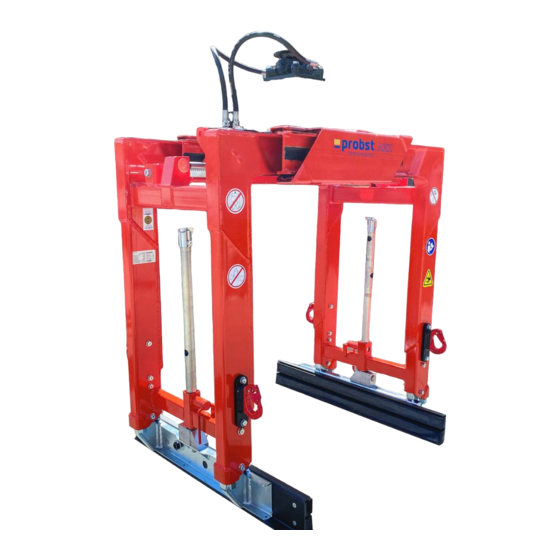
- Page 141 Arbeitsdruck / Work Pressure: min. max. Eigengewicht / Dead Weight: XXXXX kg / XXXXX Product Name: Block Loading Grab AKZ-UNI-H © all rights reserved conform to ISO 16016 Datum Name Benennung Aufbaukranzange AKZ-UNI-H Erst. 14.4.2022 R.Seidel Gepr. 19.4.2022 R.Seidel...
- Page 142 20000068 22200039 46100079 46100431 46100452 20450007 20000023 20100008 20100018 36400430 © all rights reserved conform to ISO 16016 Datum Name Benennung Aufbaukranzange AKZ-UNI-H Erst. 14.4.2022 R.Seidel Gepr. 19.4.2022 P.Hafenbrak Et 1100/1650mm, Zkl. 720 WLL 1900kg Artikelnummer/Zeichnungsnummer Blatt E56100101 Zust. Urspr.
- Page 143 Firma Probst GmbH hat den Verlust der Gewährleistung zur Folge! Warning: All valves are adjusted and under seal! Removing the seals only after approval by Probst GmbH otherwise the warranty expires WICHTIGER HINWEIS: Eine Verstellung des Bremsventils sowie des Ventils Öffnungsdruck führt zur Funktionsunfähigkeit...
- Page 144 A5610xxxx AKZ 29040082 29040211 29040204 Alle Aufkleber auf beiden Seiten der Zange/ 29041049 29040214 All stickers on both sides of the gripper 29040107 29040820 Auf beiden Seiten / on both sides Typenschild 29040056 Erstellt/Created: Zuletzt geändert/Last changed: Blatt / Sheet: 1 / 1 24.01.2017 / Krasnikov, Igor 24.01.2022 / Simon, Swen...
Need help?
Do you have a question about the AKZ-UNI-H and is the answer not in the manual?
Questions and answers