Fronius TransSteel 3500 Syn Operating Instructions Manual
Hide thumbs
Also See for TransSteel 3500 Syn:
- Operating instructions manual (132 pages) ,
- Quick manuals (2 pages)

Related Manuals for Fronius TransSteel 3500 Syn


Summary of Contents for Fronius TransSteel 3500 Syn
- Page 1 Operating instructions TransSteel 3500 Syn TransSteel 5000 Syn Operating instructions 42,0426,0258,EN 017-02052022...
-
Page 3: Table Of Contents
Contents Safety rules Explanation of safety notices General Proper use Environmental conditions Obligations of the operator Obligations of personnel Mains connection Protecting yourself and others Danger from toxic gases and vapours Danger from flying sparks Risks from mains current and welding current Meandering welding currents EMC Device Classifications EMC measures... - Page 4 Keylock Connections, switches and mechanical components TSt 3500/5000 Syn power source Installation and commissioning Minimum equipment needed for welding task General Gas-cooled MIG/MAG welding MIG/MAG welding, water-cooled MMA welding Before installation and commissioning Safety Utilisation for intended purpose only Setup regulations Mains connection Connecting the mains cable Safety...
- Page 5 Safety Preparation Arc air gouging Easy Documentation General General Documented welding data New CSV file PDF report / Fronius signature Activating / deactivating Easy Documentation Setting the date and time Deactivating Easy Documentation Setup settings Setup menu General remarks Operation...
- Page 6 TSt 5000 MV Syn Overview with critical raw materials, year of production of the device Welding program tables TransSteel 3500 Syn - Euro welding program tables TransSteel 5000 Syn - Euro welding program tables TransSteel 3500 Syn - US welding program tables...
-
Page 7: Safety Rules
Safety rules Explanation of DANGER! safety notices Indicates immediate danger. ▶ If not avoided, death or serious injury will result. WARNING! Indicates a potentially hazardous situation. ▶ If not avoided, death or serious injury may result. CAUTION! Indicates a situation where damage or injury could occur. ▶... -
Page 8: Proper Use
Proper use The device is to be used exclusively for its intended purpose. The device is intended solely for the welding processes specified on the rating plate. Any use above and beyond this purpose is deemed improper. The manufacturer shall not be held liable for any damage arising from such usage. Proper use includes: carefully reading and following all the instructions given in the operating in- structions... -
Page 9: Mains Connection
Before leaving the workplace, ensure that people or property cannot come to any harm in your absence. Mains connec- Devices with a higher rating may affect the energy quality of the mains due to tion their current consumption. This may affect a number device types in terms of: Connection restrictions Criteria with regard to the maximum permissible mains impedance Criteria with regard to the minimum short-circuit power requirement... -
Page 10: Danger From Toxic Gases And Vapours
Danger from tox- The fumes produced during welding contain harmful gases and vapours. ic gases and va- Welding fumes contain substances that cause cancer, as stated in Monograph pours 118 of the International Agency for Research on Cancer. Use at-source extraction and a room extraction system. If necessary, use a welding torch with an integrated extraction device. -
Page 11: Risks From Mains Current And Welding Current
Do not carry out welding on containers that are being or have been used to store gases, propellants, mineral oils or similar products. Residues pose an explosive hazard. Risks from mains An electric shock is potentially life threatening and can be fatal. current and Do not touch live parts either inside or outside the device. -
Page 12: Meandering Welding Currents
If work on live parts is required, appoint a second person to switch off the main switch at the right moment. Meandering If the following instructions are ignored, meandering welding currents can devel- welding currents op with the following consequences: Fire hazard Overheating of parts connected to the workpiece Damage to ground conductors... -
Page 13: Emf Measures
Welding power-leads must be kept as short as possible must be laid close together (to avoid EMF problems) must be kept well apart from other leads Equipotential bonding Earthing of the workpiece If necessary, establish an earth connection using suitable capacitors. Shield, if necessary Shield other devices nearby Shield the entire welding installation... -
Page 14: Requirement For The Shielding Gas
Risk of scalding from escaping coolant. Switch off cooling unit before discon- necting coolant flow or return lines. Observe the information on the coolant safety data sheet when handling coolant. The coolant safety data sheet may be obtained from your service centre or down- loaded from the manufacturer's website. -
Page 15: Danger From Escaping Shielding Gas
Only use shielding gas cylinders suitable for the application in hand, along with the correct and appropriate accessories (regulator, hoses and fittings). Only use shielding gas cylinders and accessories that are in good condition. Turn your face to one side when opening the valve of a shielding gas cylinder. Close the shielding gas cylinder valve if no welding is taking place. -
Page 16: Safety Measures In Normal Operation
Safety measures Only operate the device when all safety devices are fully functional. If the safety in normal opera- devices are not fully functional, there is a risk of tion injury or death to the operator or a third party damage to the device and other material assets belonging to the operator inefficient operation of the device Any safety devices that are not functioning properly must be repaired before... -
Page 17: Safety Inspection
(e.g. relevant product standards of the EN 60 974 series). Fronius International GmbH hereby declares that the device is compliant with Directive 2014/53/EU. The full text on the EU Declaration of Conformity can be found at the following address: http://www.fronius.com Devices marked with the CSA test mark satisfy the requirements of the relevant standards for Canada and the USA. -
Page 19: General Information
General information... -
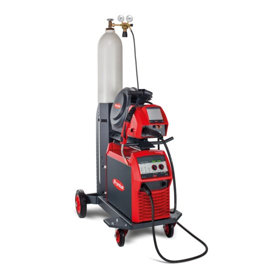
Page 21: General
General Device concept The TransSteel (TSt) 3500 Syn and TSt 5000 Syn power sources are fully di- gitised, microprocessor-controlled in- verter power sources. The modular design and potential for system add-ons ensure a high degree of flexibility. The devices are designed for the weld- ing of steel and the following welding processes: MAG welding... - Page 22 Warning notices affixed to the power source Welding is dangerous. The following basic requirements must be met: Welders must be sufficiently qualified Suitable protective equipment must be used All persons not involved in the welding process must be kept at a safe dis- tance Do not use the functions described here until you have fully read and understood the following documents:...
-
Page 23: Welding Processes, Procedures And Welding Characteristics For Mig/Mag Welding
Welding processes, procedures and welding char- acteristics for MIG/MAG welding General Power sources offer a selection of welding processes, procedures and welding characteristics that enable a wide range of materials to be processed in the most effective way. Welding charac- When selecting the filler metal, various process-optimised welding character- teristics istics are available depending on the welding process and shielding gas combin-... -
Page 24: System Components
System components General The power sources can be operated with various system components and op- tions. This makes it possible to optimise procedures and to simplify machine handling and operation, as necessitated by the particular field of application in which the power source is to be used. Safety WARNING! Danger from incorrect operation and work that is not carried out properly. - Page 25 Welding torch Wirefeeder Wirefeeder holder Interconnecting hosepacks Power source Cooling unit Trolley and gas cylinder holders Grounding cable and electrode cable...
-
Page 26: Options
Options General The options listed below are available with all power source variants. Machine inter- The machine interface connects the power source to the machine control. The face following signals can be transmitted across the machine interface: Signal input: Start of welding / end of welding Signal input for a floating contact (sensor, relay, etc.) between pin X1:1 and pin X1:2 The machine control signal input is processed by the power source in the... -
Page 27: Keylock Switch
Keylock switch An optional keylock switch is available for the power source to prevent the set- tings from being inadvertently changed on the control panel. If the keylock switch is in the horizontal position, no settings can be set on the control panel, only parameter settings can be retrieved, any assigned "Save"... -
Page 28: Vrd: Safety Principle
VRD: safety The welding circuit resistance is great- principle er than the minimum human body res- istance (greater than or equal to 200 Ohm): VRD is active Open circuit voltage is limited to 35 V Unintentional contact with the output voltage does not put the welder at risk The welding circuit resistance is less than the minimum human body resist-... -
Page 29: Control Elements And Connections
Control elements and connections... -
Page 31: Synergic Control Panel
Synergic control panel General The functions on the control panel are all arranged in a logical way. The various welding parameters can easily be selected using buttons and can just as easily be altered using buttons or the adjusting dial displayed on the digital display during welding The synergic function ensures that all other welding parameters are adjusted whenever an individual parameter is changed. -
Page 32: Synergic Control Panel
Synergic control panel (13) (14) (15) (16) (12) (11) (10) "Parameter selection" button (right) a) for selecting the following welding parameters Arc length correction for correcting the arc length Welding voltage in V *) Before the start of welding, the device automatically displays a standard value based on the programmed parameters. - Page 33 Welding current *) Welding current in A Before the start of welding, the device automatically displays a standard value based on the programmed parameters. During welding, the actual value is displayed. Wire speed *) Wire speed in m/min or ipm. b) for changing parameters in the Setup menu Adjusting dial (right) for changing the arc length correction, welding voltage and arc-force...
- Page 34 "Wire threading" button (11) Press and hold the button: gasless wire threading into the torch hosepack While the button is being held, the wire drive operates at feeder inching speed. (12) "Gas-test" button For setting the necessary gas flow rate on the pressure regulator. Press the button once: shielding gas flows out Press the button again: shielding gas flow stops If the "Gas-test"...
-
Page 35: Service Parameters
Service para- Various service parameters can be retrieved by pressing the "Parameter selec- meters tion" buttons at the same time. Opening the display The first parameter ("Firmware ver- sion") is displayed, e.g. "1.00 | 4.21" Selecting parameters Use the "Mode" and "Process" buttons or the left-hand adjusting dial to select the required Setup parameter Available parameters... -
Page 36: Keylock
Keylock A keylock can be selected to prevent the settings from being inadvertently changed on the control panel. As long as the keylock is active No settings can be made on the control panel Only parameter settings can be retrieved Any assigned "Save"... -
Page 37: Connections, Switches And Mechanical Components
Connections, switches and mechanical compon- ents TSt 3500/5000 Syn power source (-) - current socket with bayonet latch Used for Connecting the grounding cable during MIG/MAG welding Connecting the electrode cable or grounding cable during manual metal arc welding (depending on the type of electrode used) Mains switch For switching the power source on and off (+) - current socket with bayonet latch... -
Page 39: Installation And Commissioning
Installation and commissioning... -
Page 41: Minimum Equipment Needed For Welding Task
Minimum equipment needed for welding task General Depending on which welding process you intend to use, a certain minimum equip- ment level will be needed in order to work with the power source. The welding processes and the minimum equipment levels required for the weld- ing task are then described. -
Page 42: Before Installation And Commissioning
Before installation and commissioning Safety WARNING! Danger from incorrect operation and work that is not carried out properly. This can result in serious personal injury and damage to property. ▶ All the work and functions described in this document must only be carried out by technically trained and qualified personnel. -
Page 43: Mains Connection
WARNING! Danger from electrical current due to electrically conductive dust in the device. This can result in serious injury and damage to property. ▶ Only operate the device with an air filter fitted. The air filter is a very import- ant safety device for achieving IP 23 protection. -
Page 44: Connecting The Mains Cable
Connecting the mains cable Safety WARNING! Danger due to work that has been carried out incorrectly. This can result in serious injury and damage to property. ▶ The work described below must only be carried out by trained and qualified personnel. -
Page 45: Connecting The Mains Cable
TSt 5000 MV 3 x 208 / 230 / 400 / 460 AWG 6 *) 4G10 Canada / US cable type: Extra-hard usage The item numbers of the different cables can be found in the Spare Parts List of the device. AWG ... -
Page 46: Fitting The Canada/Us Strain-Relief Device
1,2 Nm IMPORTANT! Tie the phase conduct- ors near the block terminals using cable ties. Fitting the Canada/US strain-relief device... - Page 47 3,5 Nm IMPORTANT! Tie the phase conduct- ors near the block terminals using cable ties.
-
Page 48: Generator-Powered Operation
Generator-powered operation Generator- The power source is generator-compatible. powered opera- tion The maximum apparent power S of the power source must be known in order 1max to select the correct generator output. The maximum apparent power S of the power source is calculated as follows: 1max 3-phase devices: S x √3... -
Page 49: Start-Up
Start-up General Commissioning a power source is described by reference to a manual water- cooled MIG/MAG application. Information on The steps and activities described below include references to various system system compon- components, including: ents trolley upright console cooling units wire-feed units interconnecting hosepacks welding torches, etc. -
Page 50: Placing The Wirefeeder On The Power Source
Placing the CAUTION! wirefeeder on the power source Risk of injury and material damage from falling wirefeeder. ▶ Make sure that the wirefeeeder is located securely on the swivel pin and that the devices, upright consoles and trolleys are stable. -
Page 51: Fitting The Interconnecting Hosepack Strain-Relief Device
Fitting the inter- connecting hosepack strain- relief device Fitting the strain-relief device to the trolley Fitting the strain-relief device to the wirefeeder IMPORTANT! To prevent wear and tear, leave some slack when connecting the cables. A strain-relief device is not provided for 1.2 m (3 ft 11.24 in.) intercon- necting hosepacks. -
Page 52: Connecting The Gas Cylinder
Connecting the WARNING! gas cylinder There is a high risk of very serious injury and damage if a gas cylinder falls over. When using gas cylinders: ▶ Place them on a solid, level surface in such a way that they remain stable ▶... -
Page 53: Establishing A Ground Earth Connection
Establishing a NOTE! ground earth connection When establishing a ground earth connection, observe the following points: ▶ Use a separate grounding cable for each power source ▶ Keep the plus cable and grounding cable together as long and as close as possible ▶... -
Page 54: Connecting Mig/Mag Welding Torches
Connecting * when the optional water connection MIG/MAG weld- and the water-cooled welding torch are ing torches fitted Inserting/repla- CAUTION! cing feed rollers Danger from feed roller holders flying upwards. This can result in injuries. ▶ When unlocking the clamping lever, keep fingers away from the area to the left and right of the lever. -
Page 55: Inserting The Wirespool
Inserting the CAUTION! wirespool Risk of injury due to springiness of spooled wire electrode. ▶ While inserting the wirespool, hold the end of the wire electrode firmly to avoid injuries caused by the wire springing back. CAUTION! Risk of injury from falling wirespool. ▶... -
Page 56: Inserting The Basket-Type Spool
Inserting the CAUTION! basket-type spool Risk of injury due to springiness of spooled wire electrode. ▶ When inserting the basket-type spool, hold the end of the wire electrode firmly to avoid injuries caused by the wire springing back. CAUTION! Risk of injury from falling basket-type spool. ▶... -
Page 57: Feeding In The Wire Electrode
CAUTION! Risk of injury and material damage from falling basket-type spool. ▶ Place the basket-type spool on the adapter provided in such a way that the bars on the spool are inside the adapter guideways. Feeding in the CAUTION! wire electrode Risk of injury due to springiness of spooled wire electrode. - Page 58 CAUTION! Risk of injury from emerging wire electrode. ▶ When pressing the wire threading button or the torch trigger, keep the weld- ing torch away from your face and body, and wear suitable protective goggles. IMPORTANT! To facilitate the exact positioning of the wire electrode, the follow- ing sequences are possible when the wire threading button is pressed and held down.
-
Page 59: Setting The Contact Pressure
If the torch trigger is held down, wirefeeding restarts immediately without shield- ing gas and welding voltage, and the process continues as described above. Setting the con- CAUTION! tact pressure Risk from excessive contact pressure. This can result in severe damage to property and poor weld properties. ▶... -
Page 60: Design Of The Brake
STOP STOP Design of the WARNING! brake Danger from incorrect installation. This can result in severe personal in- jury and damage to property. ▶ Do not dismantle the brake. ▶ Maintenance and servicing of brakes is to be carried out by trained, qualified personnel only. -
Page 61: Welding
Welding... -
Page 63: Power Limitation
Power limitation Safety function "Power limitation" is a safety function for MIG/MAG welding. This means that the power source can be operated at the power limit whilst maintaining process safety. Wire speed is a determining parameter for welding power. If it is too high, the arc gets smaller and smaller and may be extinguished. -
Page 64: Mig/Mag Modes
MIG/MAG modes General WARNING! Operating the equipment incorrectly can cause serious injury and damage. ▶ Do not use the functions described here until you have read and completely understood these Operating Instructions. ▶ Do not use the functions described here until you have fully read and under- stood all of the Operating Instructions for the system components, in partic- ular the safety rules. -
Page 65: 2-Step Mode
2-step mode "2-step mode" is suitable for Tacking work Short weld seams Automated and robot welding 4-step mode "4-step mode" is suitable for longer weld seams. -
Page 66: Special 4-Step Mode
Special 4-step mode Special 4-step mode allows the starting and final current to be configured in ad- dition to the advantages of 4-step mode. Spot welding < SPt The "Spot welding" mode is suitable for welded joints on overlapped sheets. Start by pressing and releasing the torch trigger - GPr gas pre-flow time - Weld- ing current phase for the duration of the SPt spot welding time - GPo gas post- flow. -
Page 67: 2-Step Stitch Welding
2-step stitch welding 2-step stitch welding The "2-step stitch welding" mode is suitable for welding short weld seams on thin sheets, to prevent the weld seams from dropping through the base material. 4-step stitch welding 4-step stitch welding The "4-step stitch welding" mode is suitable for welding longer weld seams on thin sheets, to prevent the weld seams from dropping through the base material. -
Page 68: Mig/Mag Welding
MIG/MAG welding Safety WARNING! Danger from incorrect operation and work that is not carried out properly. This can result in serious personal injury and damage to property. ▶ All the work and functions described in this document must only be carried out by technically trained and qualified personnel. -
Page 69: Mig/Mag Standard Synergic Welding
MIG/MAG standard synergic welding MIG/MAG Press the "Material" button to select the filler metal to be used. standard syner- Press the "Wire diameter" button to select the diameter of the wire elec- gic welding trode used. Press the "Shielding gas" button to select the shielding gas to be used. The assignment of the SP position is in the welding program tables in the appendix. -
Page 70: Corrections During Welding
CAUTION! Risk of injury and damage from electric shock and from the wire electrode emerging from the torch. When pressing the torch trigger ▶ keep the welding torch away from your face and body ▶ wear suitable protective goggles ▶ do not point the welding torch at people ▶... -
Page 71: Mig/Mag Standard Manual Welding
MIG/MAG standard manual welding General The MIG/MAG standard manual welding process is a MIG/MAG welding process with no synergic function. Changing one parameter does not result in any automatic adjustments to the other parameters. All of the variable parameters must therefore be adjusted indi- vidually, as dictated by the welding process in question. -
Page 72: Corrections During Welding
All welding parameter set values remain stored until the next time they are changed. This applies even if the power source is switched off and on again. To display the actual welding current during welding, select the welding current parameter. To display the actual welding current during welding: Press the "Parameter selection"... -
Page 73: Spot And Stitch Welding
Spot and stitch welding General The spot and stitch welding modes are MIG/MAG welding processes. The spot and stitch welding modes can be activated on the power source control panel. Spot welding is used on welded joints on overlapped sheets that are only access- ible on one side. -
Page 74: Stitch Welding
Spot welding Procedure for producing a welding spot: Hold the welding torch vertical Press and release the torch trigger Keep the welding torch in the same position Wait for the gas post-flow time Raise the welding torch Stitch welding Activating stitch welding mode: For the SPt Setup parameter (spot / stitch welding time), enter a value >... - Page 75 Procedure for stitch welding: Hold the welding torch vertical Depending on the selected mode: press and hold the torch trigger (2-step mode) press and release the torch trigger (4-step mode) Keep the torch in the same position Wait for the welding interval Position the welding torch at the next point To end stitch welding, depending on the selected mode: release the torch trigger (2-step mode)
-
Page 76: Easyjob Mode
EasyJob mode General The "Save" buttons allow up to 5 EasyJob operating points to be saved. Every op- erating point matches the settings on the control panel. EasyJobs can be stored for each welding process. IMPORTANT! Setup parameters are not saved at this time. Storing EasyJob Press and hold one of the "Save"... - Page 77 In addition to the "Save" button number lighting up, a number is displayed dir- ectly on the Up/Down welding torch: Indicator on the Up/Down welding EasyJob operating point on the con- torch trol panel...
-
Page 78: Mma Welding
MMA welding Safety WARNING! Danger from incorrect operation and work that is not carried out properly. This can result in serious personal injury and damage to property. ▶ All the work and functions described in this document must only be carried out by technically trained and qualified personnel. -
Page 79: Corrections During Welding
Move the mains switch to the "I" position: all the indicators on the control panel will briefly light up Press the "Process" button to select the MMA welding process: The welding voltage is applied to the welding socket with a three second time lag. -
Page 80: Hotstart Function
HotStart func- To obtain optimum welding results, it will sometimes be necessary to adjust the tion HotStart function. Advantages Improved ignition properties, even when using electrodes with poor ignition properties Better fusion of the base material during the start-up phase, meaning fewer cold-shut defects Largely prevents slag inclusions For details on setting the available welding parameters, please refer to "Setup... -
Page 81: Arc Air Gauging (Tst 5000 Syn)
Arc Air Gauging (TSt 5000 Syn) Safety WARNING! Danger from incorrect operation and work that is not carried out properly. This can result in serious personal injury and damage to property. ▶ All the work and functions described in this document must only be carried out by technically trained and qualified personnel. -
Page 82: Arc Air Gouging
Arc air gouging CAUTION! Risk of injury and damage from electric shock. As soon as the mains switch is in the "I" position, the electrode in the arc air gou- ging torch is live. ▶ Make sure the electrode does not touch any persons or electrically conduct- ing or earthed parts (e.g. - Page 83 The arc air gouging parameters are the same as the welding parameters for MMA welding, see page 96.
-
Page 85: Easy Documentation
Easy Documentation... -
Page 87: General
CSV file on a USB flash drive. A Fronius signature is stored with the welding data which can be used to check and guarantee the authenticity of the data. -
Page 88: New Csv File
By scanning the link on the left Fronius signa- A PDF report of the selected welding data can be created ture The authenticity of the data can be checked and guaran- teed via the Fronius signature read out with the welding data. https://easydocu.weldcube.com... -
Page 89: Activating / Deactivating Easy Documentation
Activating / deactivating Easy Documentation Setting the date The date and time are set in the 2nd level of the service menu. and time The first parameter in the service menu is displayed. Select the "2nd" setup parameter us- ing the left-hand adjusting dial The first parameter in the 2nd level of the service menu is displayed. - Page 90 Unplug the USB flash drive from the power source The following appears on the power source display: Easy Documentation is deactivated. Confirm the display by pressing the arrow key...
-
Page 91: Setup Settings
Setup settings... -
Page 93: Setup Menu
Setup menu General remarks The Setup menu provides simple access to expert knowledge in the power source and to additional functions. The Setup menu can be used to make simple adjust- ments of the parameters to suit the various job settings. Operation Access to the setup menu is described based on the MIG/MAG standard synergic welding process. - Page 94 Setting range: 1 - max. (39.37 - max.) Factory setting: 10 (393.7) Burn-back time correction Burn-back time effect due to a delayed switch-off of the welding current after the wire electrode stops being fed forward. A ball forms on the wire electrode.
-
Page 95: Setup Parameters For Mig/Mag Standard Synergic Welding
Setup menu (2nd) are also not deleted. Exception: Ignition time-out func- tion parameter (ito). Second level of the Setup menu (see "Setup menu - level 2") Setup paramet- "Min." and "max." are used for setting ranges that differ according to power ers for source, welding program, etc. -
Page 96: Setup Parameters For Mma Welding
Ignition time-out function - length of wire that is fed before the safety cut-out trips Unit: mm (in.) Setting range: OFF, 5 - 100 (OFF, 0.2 - 3.94) Factory setting: OFF NOTE! The "Ignition time-out" function (ito) is a safety function. The length of wire that is fed before the safety cut-out trips may differ from the pre-set wire length, particularly when the wire is being fed at fast wire speeds. - Page 97 Factory setting: OFF Gouging (Arc Air Gauging) Arc air gouging with a carbon electrode, e.g., for joint preparation Unit: - Setting range: on / oFF Factory setting: oFF Reset power source to factory settings Press and hold down one of the "Parameter selection" buttons for 2 s to restore the factory settings - when "PrG"...
-
Page 98: Setup Menu - Level 2
Setup menu - Level 2 Operation (level To access the Level 2 Setup menu: 2 Setup menu) Use the "Process" button to select the "MIG/MAG standard synergic welding" process The control panel is now in the Setup menu for the "MIG/MAG standard syn- ergic welding"... - Page 99 Parameters for Cooling unit Control MIG/MAG weld- (only with connected cooling unit) ing in the Setup menu level 2 Unit: - Setting range: Aut, On, OFF Factory setting: Aut Aut: The cooling unit cuts out after a 2-minute welding off-time. IMPORTANT! If the coolant temperature and flow monitoring options have been installed in the cooling unit, the cooling unit cuts out as soon as the return-flow temperature drops below 50 °C, but at the earliest...
- Page 100 Real Energy Input – electrical energy of the arc relative to the welding speed Unit: kJ Setting range: ON / OFF Factory setting: OFF Since the full range of values (1 kJ - 99999 kJ) cannot be displayed on the three-digit display, the following display format has been selected: Value in kJ / indicator on display: 1 to 999 / 1 to 999 1000 to 9999 / 1.00 to 9.99 (without "ones"...
- Page 101 EasyJob Trigger - for activating / deactivating the switching of Easy- Jobs by means of the torch trigger Unit: - Setting range: ON / OFF Factory setting: OFF Function with MIG/MAG torch trigger Press torch trigger briefly (< 0.5 s) No welding operation: All MIG/MAG EasyJobs are switched through in succession.
-
Page 102: Measuring Welding Circuit Resistance R
Measuring welding circuit resistance r General Measuring the welding circuit resistance makes it possible to have a consistent welding result at all times, even with hosepacks of different lengths. The welding voltage at the arc is then always precisely regulated, regardless of the length and cross-sectional area of the hosepack. - Page 103 Fit the gas nozzle back onto the welding torch...
-
Page 104: Retrieving The Welding Circuit Inductivity L
Retrieving the welding circuit inductivity L General Laying of the hosepacks has a significant effect on welding circuit inductivity and therefore affects the welding process. It is important to lay the hosepacks cor- rectly in order to obtain the best possible welding result. Displaying weld- The setup parameter "L"... -
Page 105: Troubleshooting And Maintenance
Troubleshooting and maintenance... -
Page 107: Troubleshooting
Troubleshooting General The devices are equipped with an intelligent safety system. This means that to a large extent it has been possible to dispense with melting-type fuses. Melting- type fuses therefore no longer need to be replaced. After a possible malfunction has been remedied, the device is ready for use again. - Page 108 Power source does not function Mains switch is on, but indicators are not lit up Cause: There is a break in the mains lead; the mains plug is not plugged in Remedy: Check the mains lead, ensure that the mains plug is plugged in Cause: Mains socket or mains plug faulty Remedy:...
- Page 109 No welding current Mains switch is ON and indicators are lit up Cause: Grounding (earthing) connection is incorrect Remedy: Check the grounding (earthing) connection for correct polarity Cause: There is a break in the power cable in the welding torch Remedy: Replace the welding torch No protective gas shield...
-
Page 110: Displayed Service Codes
Welding torch becomes very hot Cause: Welding torch is inadequately dimensioned Remedy: Observe the duty cycle and loading limits Cause: Only on water-cooled systems: inadequate coolant flow Remedy: Check coolant level, coolant flow, for coolant contamination, etc. For further information refer to the cooling unit Operating Instructions Poor weld properties Cause: Incorrect welding parameters... - Page 111 ----- Cause: An invalid welding process was called up on the robot interface (no. 37) or an empty flag was selected (no. 32) Remedy: Call up a valid welding process or select assigned "Save" button ELn | 8 Cause: The connected wire-feed unit is not supported Remedy: Connect supported wire-feed unit ELn | 12...
- Page 112 no | UrL Cause: The VRD option has tripped too early. Remedy: Check whether all welding power-leads and control lines are connec- ted. Switch off the power source Wait 10 seconds and switch the power source back on again If the error occurs again - contact After Sales Service. E-Stop Cause: "External stop"...
- Page 113 to0 | xxx Note: xxx stands for a temperature value Cause: Overtemperature in the primary circuit of the power source Remedy: Allow power source to cool down, check air filter and clean if neces- sary, check that fan is on to1 | xxx Note: xxx stands for a temperature value Cause:...
- Page 114 tu0 | xxx Remark: xxx stands for a temperature value Cause: Undertemperature in the power source primary circuit Remedy: Place power source in a heated room and allow to warm up tu1 | xxx Note: xxx stands for a temperature value Cause: Undertemperature on the booster located in the power source Remedy:...
-
Page 115: Displayed Service Codes In Connection With Opt Easy Documentation
hot | H2O Cause: The coolant temperature is too high Remedy: Allow cooling unit and cooling circuit to cool down, until "hot | H2O" is no longer displayed. Open the cooling unit and clean the cooler, check fan is working properly. Robot interface or field bus coupler: before resuming welding, set the "Source error reset"... - Page 116 bAt | oFF Welding is not possible. Cause: The battery of the OPT Easy Documentation is empty Remedy: To reset the service code, press the arrow key - the display shows no | dAt; Contact service (to change the battery); After changing the battery, set the date and time in the 2nd level of the service menu;...
-
Page 117: Care, Maintenance And Disposal
Care, maintenance and disposal General Under normal operating conditions, the welding system requires only a minimum of care and maintenance. However, it is vital to observe some important points to ensure the welding system remains in a usable condition for many years. Safety WARNING! Danger from electrical current. -
Page 118: Every 6 Months
Every 6 months CAUTION! Danger due to the effect of compressed air. This can result in damage to property. ▶ Do not bring the air nozzle too close to electronic components. Dismantle device side panels and clean inside of device with dry, reduced compressed air If a lot of dust has accumulated, clean the cooling air ducts WARNING! -
Page 119: Appendix
Appendix... -
Page 121: Average Consumption Values During Welding
Average consumption values during welding Average wire Average wire electrode consumption at a wire speed of 5 m/min electrode con- 1.0 mm wire 1.2 mm wire 1.6 mm wire sumption during electrode dia- electrode dia- electrode dia- MIG/MAG weld- meter meter meter Steel wire electrode... -
Page 122: Technical Data
Technical data Special voltages For devices designed for special voltages, the technical data on the rating plate applies. For all machines with a permitted mains voltage of up to 460 V: The standard mains plug allows the user to operate with a mains voltage of up to 400 V. For mains voltages up to 460 V fit a mains plug permitted for such use or install the mains supply directly. -
Page 123: Tst 3500 Syn
TSt 3500 Syn Mains voltage (U 380 V 400 V 460 V Max. effective primary current (I 15.0 A 14.4 A 12.6 A 1eff Max. primary current (I 23.6 A 22.7 A 19.8 A 1max Mains fuse protection 35 A slow-blow Mains voltage tolerance -10 / +15% Grid frequency... -
Page 124: Tst 3500 Mv Syn
TSt 3500 MV Mains voltage (U 200 V 230 V Max. effective primary current (I 24.1 A 20.8 A 1eff Max. primary current (I 38.1 A 32.9 A 1max Mains fuse protection 35 A slow-blow Mains voltage (U 400 V 460 V Max. -
Page 125: Tst 5000 Syn
TSt 5000 Syn Mains voltage (U 380 V 400 V 460 V Max. effective primary current (I 27 A 25.9 A 23.2 A 1eff Max. primary current (I 42.7 A 41.0 A 36.7 A 1max Mains fuse protection 35 A slow-blow Mains voltage tolerance -10 / +15% Grid frequency... -
Page 126: Tst 5000 Mv Syn
TSt 5000 MV Mains voltage (U 200 V 230 V Max. effective primary current (I 39.5 A 36.3 A 1eff Max. primary current (I 66.7 A 57.4 A 1max Mains fuse protection 63 A slow-blow Mains voltage (U 400 V 460 V Max. - Page 127 An overview of which critical raw materials are contained in this device can be terials, year of found at the following Internet address. production of www.fronius.com/en/about-fronius/sustainability. the device To calculate the year of production of the device: Each device is provided with a serial number...
-
Page 128: Welding Program Tables
Welding program tables TransSteel 3500 Welding programs are active if Syn - Euro weld- the Setup parameter "SEt" is set to "Std" (Standard), ing program tables the VR 5000 Remote wirefeeder is fitted with the Synergic Steel control panel option. Welding program database: UID 3431 Pos. - Page 129 Special assignment Material Diameter 0,8 mm 0,9 mm 1,0 mm 1,2 mm 1,4 mm 1,6 mm Pos. Pos. .030‘‘ .035‘‘ .040‘‘ .045‘‘ .052‘‘ 1/16‘‘ Stainless Steel Ar + 2,5 % CO2 2427 2402 2426 2405 Stainless Steel root Ar + 2,5 % CO2 2440 2441 2442...
-
Page 130: Transsteel 5000 Syn - Euro Welding Program Tables
TransSteel 5000 Welding programs are active if Syn - Euro weld- the Setup parameter "SEt" is set to "Std" (Standard), ing program tables the VR 5000 Remote wirefeeder is fitted with the Synergic Steel control panel option. Welding program database: UID 3430 Pos. - Page 131 Special assignment Material Diameter 0,8 mm 0,9 mm 1,0 mm 1,2 mm 1,4 mm 1,6 mm Pos. Pos. .030‘‘ .035‘‘ .040‘‘ .045‘‘ .052‘‘ 1/16‘‘ Stainless Steel Ar + 2,5 % CO2 2427 2402 2426 2405 2428 Stainless Steel root Ar + 2,5 % CO2 2440 2441 2442...
-
Page 132: Transsteel 3500 Syn - Us Welding Program Tables
TransSteel 3500 Welding programs are active if Syn - US welding the Setup parameter "SEt" is set to "US" (USA), program tables the VR 5000 Remote wirefeeder is fitted with the Synergic US control panel option. Welding program database: UID 3431 Pos. - Page 133 Special assignment Material Diameter 0,8 mm 0,9 mm 1,0 mm 1,2 mm 1,4 mm 1,6 mm Pos. Pos. .030‘‘ .035‘‘ .040‘‘ .045‘‘ .052‘‘ 1/16‘‘ Stainless Steel root Ar + 2,5 % CO2 2440 2441 2442 2443 FCW Stainless Steel Ar + 18 % CO2 2423 2424 2425...
-
Page 134: Transsteel 5000 Syn - Us Welding Program Tables
TransSteel 5000 Welding programs are active if Syn - US welding the Setup parameter "SEt" is set to "US" (USA), program tables the VR 5000 Remote wirefeeder is fitted with the Synergic US control panel option. Welding program database: UID 3430 Pos. - Page 135 Special assignment Material Diameter 0,8 mm 0,9 mm 1,0 mm 1,2 mm 1,4 mm 1,6 mm Pos. Pos. .030‘‘ .035‘‘ .040‘‘ .045‘‘ .052‘‘ 1/16‘‘ Stainless Steel root Ar + 2,5 % CO2 2440 2441 2442 2443 FCW Stainless Steel Ar + 18 % CO2 2423 2424 2425...
-
Page 136: Transsteel 3500 Yard Welding Program Tables
TransSteel 3500 Welding programs are active if a VR 5000 Remote wirefeeder with the Synergic Yard welding YARD control panel option is in the system. program tables Welding program database: UID 3431 In this case, the welding program Pos. display on the power source is deac- tivated. -
Page 137: Transsteel 5000 Yard Welding Program Tables
TransSteel 5000 Welding programs are active if a VR 5000 Remote wirefeeder with the Synergic Yard welding YARD control panel option is in the system. program tables Welding program database: UID 3430 In this case, the welding program in- Pos. dication on the power source is de- activated. -
Page 138: Standard Value Tables For Mig/Mag Standard Manual Welding
Standard value tables for MIG/MAG standard manual welding Settings tables Shielding gas: Argon + CO Material: G3 Si 1 Wire diameter: 0.8 mm (.03 in.) Ignition current: 400 A Sheet thickness Wire feed speed Welding voltage Dynamic 0.8 mm (.03 in.) 2.1 m/min (82.68 ipm) 13.7 V 1 mm (.04 in.) - Page 139 Shielding gas: Argon + CO Material: G3 Si 1 Wire diameter: 1.0 mm (.04 in.) Ignition current: 500 A Sheet thickness Wire feed speed Welding voltage Dynamic 0.8 mm (.03 in.) 1.6 m/min (62.99 ipm) 14.3 V 1 mm (.04 in.) 2 m/min (78.74 ipm) 14.5 V 1.3 mm (.05 in.)
- Page 140 Shielding gas: Argon + CO Material: G3 Si 1 Wire diameter: 1.4 mm (.06 in.) Ignition current: 650 A Sheet thickness Wire feed speed Welding voltage Dynamic 1 mm (.04 in.) 1.2 m/min (47.24 ipm) 13.7 V 1.5 mm (.06 in.) 1.7 m/min (66.93 ipm) 15 V 2 mm (.08 in.)
- Page 141 Shielding gas: CO Material: G3 Si 1 Wire diameter: 0.8 mm (.3 in.) Ignition current: 400 A Sheet thickness Wire feed speed Welding voltage Dynamic 0.8 mm (.03 in.) 1.5 m/min (59.06 ipm) 16 V 1 mm (.04 in.) 3 m/min (118.11 ipm) 16.8 V 1.5 mm (.06 in.) 5 m/min (196.85 ipm)
- Page 142 Sheet thickness Wire feed speed Welding voltage Dynamic 1.3 mm (.05 in.) 2.6 m/min (102.36 ipm) 18.9 V 1.5 mm (.06 in.) 3.2 m/min (125.98 ipm) 20.4 V 2 mm (.08 in.) 4.8 m/min (188.98 ipm) 20.8 V 3 mm (.12 in.) 6 m/min (236.22 ipm) 21.4 V 4 mm (.16 in.)
- Page 143 Sheet thickness Wire feed speed Welding voltage Dynamic 6 mm (.24 in.) 6 m/min (236.22 ipm) 26.2 V 8 mm (.31 in.) 7.5 m/min (295.28 ipm) 29.9 V 12 mm (.47 in.) 10 m/min (393.7 ipm) 33.9 V 15 mm (.59 in.) 12.5 m/min (492.13 ipm) 36.2 V 20 mm (.79 in.)
Need help?
Do you have a question about the TransSteel 3500 Syn and is the answer not in the manual?
Questions and answers