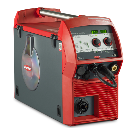
Fronius TransSteel 2700c MultiProzess Operating Instructions Manual

Fronius TransSteel 2700c MultiProzess Operating Instructions Manual

Hide thumbs Also See for TransSteel 2700c MultiProzess:
Table of Contents

Advertisement

Operating
instructions
TransSteel 2700c MultiProzess
TransSteel 2700c MV MultiProzess
TransSteel 3500c MultiProzess
EN-US
Operating instructions
42,0426,0322,EA
012-04052022

Advertisement

Table of Contents
loading
Need help?

Need help?

Do you have a question about the TransSteel 2700c MultiProzess and is the answer not in the manual?

Questions and answers

Subscribe to Our Youtube Channel

Summary of Contents for Fronius TransSteel 2700c MultiProzess

  • Page 1 Operating instructions TransSteel 2700c MultiProzess TransSteel 2700c MV MultiProzess TransSteel 3500c MultiProzess EN-US Operating instructions 42,0426,0322,EA 012-04052022...
  • Page 3: Table Of Contents

    Table of contents Safety Instructions Explanation of Safety Instructions General Intended Use Environmental Conditions Obligations of the Operating Company Obligations of Personnel Grid Connection Personal Protection and Protection of Others Danger from toxic gases and vapors Danger from Flying Sparks Risks from grid current and welding current Stray welding currents EMC Device Classifications...
  • Page 4 Manual metal arc welding TIG DC Welding Before installation and initial operation Safety Intended Use Setup regulations Grid Connection Generator-Powered Operation Generator-Powered Operation TSt 2700c MV MP - Single-Phase Operation Single-phase operation Explanation of the Term "Duty Cycle" in Single-Phase Operation Welding time in single-phase operation Connecting the Mains Cable Safety...
  • Page 5 Retrieving operating points on the Up/Down welding torch Easy Documentation (TransSteel 3500c MP) General General Documented welding data New CSV file PDF report / Fronius signature Activating / deactivating Easy Documentation Setting the date and time Deactivating Easy Documentation Setup Settings Setup Menu...
  • Page 6 Displaying the welding circuit inductivity Laying the hosepacks correctly Troubleshooting and Maintenance Troubleshooting General Safety Troubleshooting Displayed Service Codes Displayed service codes in connection with OPT Easy Documentation Service, maintenance and disposal General Safety At every start-up Whenever Required Every 2 Months Every 6 Months Disposal Appendix...
  • Page 7: Safety Instructions

    Safety Instructions Explanation of DANGER! Safety Instruc- tions Indicates an immediate danger. ▶ Death or serious injury may result if appropriate precautions are not taken. WARNING! Indicates a possibly dangerous situation. ▶ Death or serious injury may result if appropriate precautions are not taken. CAUTION! Indicates a situation where damage or injury could occur.
  • Page 8: Intended Use

    Intended Use The device is to be used exclusively for its intended purpose. The device is intended exclusively for the welding process specified on the rating plate. Utilization for any other purpose, or in any other manner, shall be deemed to be "not in accordance with the intended purpose."...
  • Page 9: Grid Connection

    Grid Connection Devices with a high output can influence the energy quality of the grid due to their current consumption. This may affect a number of device types in terms of: connection restrictions criteria regarding maximum permissible grid impedance criteria regarding the minimum required short-circuit power both at the interface with the public grid See technical data In this case, the operator or the person using the device should check whether or...
  • Page 10: Danger From Flying Sparks

    Use at-source extraction source and a room extraction system. If possible, use a welding torch with an integrated extraction device. Keep your head out of the welding fumes and gases. Take the following precautionary measures for fumes and harmful gases: Do not breathe them in.
  • Page 11 During MIG/MAG welding and TIG welding, the welding wire, the wirespool, the feed rollers, as well as all pieces of metal that are in contact with the welding wire, are live. Always place the wirefeeder on a sufficiently insulated base or use a suitable in- sulating wirefeeder holder.
  • Page 12: Stray Welding Currents

    Stray welding If the following instructions are not observed, stray welding currents may occur, currents which pose a risk of the following: Fire Overheating of parts connected to the workpiece Irreparable damage to ground conductors Damage to the device and other electrical equipment Ensure that the workpiece clamp is securely connected to the workpiece.
  • Page 13: Emf Measures

    Equipotential bonding Workpiece grounding If necessary, establish grounding using suitable capacitors. Shield, if necessary Shield other devices in the vicinity Shield the entire welding installation EMF measures Electromagnetic fields may cause health problems that are not yet known: Effects on the health of persons close by, e.g., those with pacemakers and hearing aids Persons with pacemakers must seek advice from their doctor before staying in the immediate vicinity of the device and the welding process...
  • Page 14: Requirement For The Shielding Gas

    When handling coolant, observe the information on the coolant safety data sheet. The coolant safety data sheet can be obtained from your service center or via the manufacturer's website. Only use suitable load-carrying equipment from the manufacturer to transport devices by crane. Attach chains or ropes to all designated attachments of the suitable load- carrying equipment.
  • Page 15: Danger Posed By Shielding Gas Leak

    If a valve on a shielding gas cylinder is open, turn your face away from the outlet. When no welding is taking place, close the valve of the shielding gas cylinder. Leave the cap on the valve of the shielding gas cylinder when the cylinder is not connected.
  • Page 16: Safety Measures In Normal Operation

    Safety Measures Only operate the device when all safety devices are fully functional. If the safety in Normal Oper- devices are not fully functional, there is a danger of: ation Injury or death to the operator or a third party Damage to the device and other material assets belonging to the operating company Inefficient operation of the device...
  • Page 17: Safety Inspection

    Copyright Copyright of these Operating Instructions remains with the manufacturer. Text and illustrations were accurate at the time of printing. Fronius reserves the right to make changes. The contents of the Operating Instructions shall not provide the basis for any claims whatsoever on the part of the purchaser. If you...
  • Page 19: General Information

    General information...
  • Page 21: General

    General Device Concept The TransSteel (TSt) 2700c MP and TSt 3500c MP power sources are fully digitized, microprocessor-controlled inverter power sources. A modular design and easy ability to extend the system guarantee a high degree of flexibility. The devices are designed for the welding of steel.
  • Page 22: Operating Principle

    Manual metal arc welding TSt 2700c MP TSt 3500c MP TIG welding with touchdown ignition TSt 2700c MP TSt 3500c MP Operating Prin- The central control and regulation unit of the power sources is coupled with a di- ciple gital signal processor. The central control and regulation unit and signal pro- cessor control the entire welding process.
  • Page 23: Applications

    Applications The devices are used in trade and industry for manual applications with classical steel and galvanized sheets. The TSt 2700c MP is primarily used in light-gage steel sheet (light steelwork) ap- plications. Repair, maintenance, and assembly work in shipyards, automotive suppliers, workshops or the furniture construction industry are among the typical applica- tion areas.
  • Page 24 Safety symbols on the rating plate: Welding is dangerous. The following basic requirements must be met: Adequate welding qualifications Appropriate protective equipment Exclusion of unauthorized persons Do not use the functions described here until you have fully read and understood the following documents: These Operating Instructions All system component Operating Instructions, especially the safety rules...
  • Page 25: Description Of The Warnings On The Device

    Description of Warning notices are attached to the device for certain device versions. the warnings on the device The arrangement of the symbols may vary. Warning! Caution! The symbols represent possible dangers. Drive rollers can injure fingers. The welding wire and drive parts are under welding voltage during opera- tion.
  • Page 26 Use forced-air ventilation or local extraction to remove welding fumes. Remove welding fumes with a fan. Welding sparks can cause an explosion or fire. Keep flammable materials away from the welding process. Do not perform welding near flammable materials. Welding sparks can cause a fire. Have fire extinguishers ready. If neces- sary, have a supervisor ready who can operate the fire extinguisher.
  • Page 27: System Components

    System components General The power sources can be operated with various system components and op- tions. This makes it possible to optimize procedures and to simplify machine handling and operation, depending on the field of application for the power source. Safety WARNING! Danger from incorrect operation and work that is not carried out properly.
  • Page 28 TSt 3500c MP Function MIG/MAG welding torch Stabilization of the gas cylinder holder Power source Cooling unit only TSt 3500c Trolley and gas cylinder holder Grounding and electrode cable TIG welding torch...
  • Page 29: Operating Controls And Connections

    Operating controls and connec- tions...
  • Page 31: Control Panel

    Control Panel General The functions are all arranged in a logical way on the control panel. The individual parameters required for welding can be easily selected using buttons changed using buttons or the selection dial shown on the digital display during welding The power source uses the Synergic control panel and certain general items of data such as sheet thickness, filler metal, wire diameter and shielding gas to cal- culate the best welding parameters.
  • Page 32: Synergic Control Panel

    Synergic control panel (4)(5) (17) (16) (10) (15) (14) (13) (12) (11) "Parameter selection" button (left) For selecting the following welding parameters and for changing para- meters in the Setup menu The relevant symbol lights up when a welding parameter is selected. Sheet thickness in mm or in.
  • Page 33 Intermediate arc indicator A spatter-prone "intermediate arc" occurs between the dip transfer arc and the spray arc. The intermediate arc indicator lights up to alert you to this critical area. Right digital display "Parameter selection" button (right) For selecting the following welding parameters and for changing para- meters in the Setup menu The relevant symbol lights up when a welding parameter is selected.
  • Page 34 Spot welding/stitch welding "Shielding gas" button (13) For selecting the shielding gas used. The SP parameter is reserved for additional shielding gases. The LED next to the selected shielding gas lights up. "Wire diameter" button (14) For selecting the wire diameter used. The SP parameter is reserved for additional wire diameters.
  • Page 35: Service Parameters

    Service para- Various service parameters can be retrieved by pressing the "Parameter selec- meters tion" buttons at the same time. Opening the display The first parameter "Firmware version" will be displayed, e.g., "1.00 | 4.21" Selecting parameters Use the "Mode" and "Process" buttons or the left-hand selection dial to select the required setup parameter Available parameters...
  • Page 36: Keylock

    Keylock A keylock can be selected to prevent the settings from being inadvertently changed on the control panel. As long as the keylock is active: Settings cannot be adjusted on the control panel Only parameter settings can be retrieved Any assigned "Save" button can be retrieved provided that an assigned "Save" button was selected when the keylock was enabled Activating/deactivating the keylock: Keylock activated:...
  • Page 37: Connections, Switches, And Mechanical Components

    Connections, Switches, and Mechanical Compon- ents TSt 2700c MP (11) (10) (1) (2) (3) (12) (13) * Side panel not shown LocalNet connection Standardized connection for remote control Welding torch connection For connecting the welding torch TIG Multi Connector For connecting the TIG welding torch (+) Current socket with bayonet latch Used for Connecting the polarity reverser or grounding cable for MIG/MAG...
  • Page 38: Tst 3500C Mp

    Grid cable with strain relief device Not prefitted on all models (10) Power switch For switching the power source on and off (11) LED wirespool interior lighting with the setup parameter LED the turn-off time is adjustable (12) Wirespool holder with brake For holding standard wirespools with a max.
  • Page 39 Connecting the polarity reverser or grounding cable for MIG/MAG welding (depending on the wire electrode used) Connecting the electrode cable or grounding cable for MMA welding (depending on the type of electrode used) Connecting the grounding cable for TIG welding Polarity reverser For selecting the welding potential on the MIG/MAG welding torch MIG/MAG shielding gas connection socket...
  • Page 41: Installation

    Installation...
  • Page 43: Minimum Equipment For Welding Operations

    Minimum equipment for welding operations General Depending on the welding process, a minimum level of equipment is required to work with the power source. The following describes the welding processes and the corresponding minimum equipment for welding operations. Gas-cooled Power source MIG/MAG weld- Grounding cable Gas-cooled MIG/MAG welding torch...
  • Page 44: Before Installation And Initial Operation

    Before installation and initial operation Safety WARNING! Danger from incorrect operation and work that is not carried out properly. This can result in serious personal injury and damage to property. ▶ All the work and functions described in this document must only be carried out by technically trained and qualified personnel.
  • Page 45: Grid Connection

    WARNING! Danger of electrical current due to electrically conductive dust in the device. This can result in severe personal injury and damage to property. ▶ Only operate the device if an air filter is fitted. The air filter is a very import- ant safety device for achieving IP 23 protection.
  • Page 46: Generator-Powered Operation

    Generator-Powered Operation Generator- The power source is generator-compatible. Powered Opera- tion The maximum apparent power S of the power source must be known in order 1max to select the correct generator output. The maximum apparent power S of the power source is calculated as follows: 1max Three-phase devices: S x √3...
  • Page 47: Tst 2700C Mv Mp - Single-Phase Operation

    TSt 2700c MV MP - Single-Phase Operation Single-phase op- As an alternative to three-phase operation, the multivoltage variant (MV) of the eration power source enables a welding operation with limited power or duration from just a single-phase supply. The maximum possible welding power is limited by the dimensioning of the mains fuse protection, which determines the safety cut-out of the power source.
  • Page 48: Explanation Of The Term "Duty Cycle" In Single-Phase Operation

    Grid voltage Welding process D.C. Welding current limitation Fuse rating MIG/MAG 100 * 240 V Rod electrode 20 A 100 * 100 * MIG/MAG 100 * 240 V Rod electrode 30 A 100 * 100 * D.C. = Duty cycle The 100% values relate to welding with no time limits and without cooling breaks.
  • Page 49 The following example shows the welding and pause cycles as defined in the rel- evant standards, with a welding current of 180 A and a duty cycle of 15%. I (A) 180 A 1:30 2:30 6:30 7:30 t (min:s)
  • Page 50: Welding Time In Single-Phase Operation

    Welding time in The following diagram shows the possible welding time in accordance with stand- single-phase op- ards, depending on the fuse rating and welding current. eration t (min) (4) (5) I2 (A) (1) 10 A mains fuse protection (2) 13 A mains fuse protection (3) 15 A mains fuse protection (4) 16 A mains fuse protection (5) 20 A mains fuse protection...
  • Page 51: Connecting The Mains Cable

    Connecting the Mains Cable Safety WARNING! Danger from work that is not carried out properly. This can result in severe personal injury and damage to property. ▶ The work described below may only be performed by trained specialist per- sonnel. ▶...
  • Page 52: Connecting The Grid Cable, Tst 2700C Mv, Single-Phase Operation

    American Wire Gauge Connecting the If no grid cable is connected, a grid cable that is suitable for the connection Grid Cable, TSt voltage must be fitted before commissioning. 2700c MV, Single-Phase CAUTION! Operation If no ferrules are used, there is a risk of injury and damage from short circuits between the phase conductors or between the phase conductors and the ground conductor.
  • Page 53: Connecting The Grid Cable, Tst 2700C Mp Mv

    TX25 IMPORTANT! Tie the phase conductors near the strain-relief device using cable ties. Connecting the If no grid cable is connected, a grid cable that is suitable for the connection Grid Cable, TSt voltage must be fitted before commissioning. 2700c MP MV CAUTION! If no ferrules are used, there is a risk of injury and damage from short circuits between the phase conductors or between the phase conductors and the...
  • Page 54: Connecting The Grid Cable, Tst 3500C Nc Mp

    TX25 IMPORTANT! Tie the phase conductors near the strain-relief device using cable ties. Connecting the If no grid cable is connected, a grid cable that is suitable for the connection Grid Cable, TSt voltage must be fitted before commissioning. 3500c nc MP CAUTION! If no ferrules are used, there is a risk of injury and damage from short circuits between the phase conductors or between the phase conductors and the...
  • Page 55 1,2 Nm IMPORTANT! Tie the phase conductors near the luster terminal using cable ties.
  • Page 56: Fitting/Connecting The System Components

    Fitting/Connecting the System Components Information on The steps and activities described below include references to various system System Com- components, such as ponents Trolley Cooling units (TSt 3500c only) Welding torches, etc. For more detailed information about installing and connecting the system com- ponents, please refer to the appropriate Operating Instructions for the system components.
  • Page 57: Connecting The Gas Cylinder

    Connecting the WARNING! Gas Cylinder Danger of severe injury and damage to property if gas cylinders fall over. When using gas cylinders: ▶ Place them on a solid, level surface in such a way that they remain stable ▶ Secure the gas cylinders to prevent them from falling over ▶...
  • Page 59: Mig/Mag

    MIG/MAG...
  • Page 61: Commissioning

    Commissioning General WARNING! Operating the device incorrectly can cause serious injury and damage to prop- erty. ▶ Do not use the functions described here until you have fully read and under- stood the Operating Instructions. ▶ Do not use the functions described here until you have fully read and under- stood all of the Operating Instructions of the system components, especially the safety rules.
  • Page 62: Inserting/Changing Feed Rollers

    Inserting/chan- CAUTION! ging feed rollers Risk of injury due to feed roller holders shooting upwards. ▶ When unlocking the lever, keep fingers away from the area to the left and right of the lever. In order to achieve optimum wire electrode feed, the feed rollers must be suit- able for the diameter and alloy of the wire being welded.
  • Page 63: Inserting The Wirespool/Basket-Type Spool

    Inserting the CAUTION! wirespool/ basket-type Risk of injury due to springiness of spooled wire electrode. ▶ spool When inserting the wirespool/basket-type spool, hold the end of the wire electrode firmly to avoid injuries caused by the wire electrode springing back. CAUTION! Risk of injury from falling wirespool/basket-type spool.
  • Page 64: Connecting The Gas Cylinder

    NOTE! When working with basket-type spools, only use the basket-type spool adapter supplied with the device. Inserting the basket-type spool Connecting the WARNING! Gas Cylinder Danger from falling gas cylinders. Serious personal injury and damage to property may result. ▶ Place gas cylinders on a solid, level surface so that they remain stable.
  • Page 65: Connecting The Polarity Reverser And Establishing A Ground Earth Connection

    Connecting the Connecting the Polarity Reverser Polarity Revers- er and Establish- NOTE! ing a Ground Earth Connec- If the polarity reverser is incorrectly connected, it can result in poor-quality weld properties. tion ▶ Connect the polarity reverser according to the wire electrode used. Check the wire electrode packaging to determine whether the wire electrode is for (+) or (-) welding.
  • Page 66: Feeding In The Wire Electrode

    Feeding in the CAUTION! wire electrode Risk of injury due to springiness of spooled wire electrode. ▶ When inserting the wire electrode into the 4-roller drive, hold the end of the wire electrode firmly to avoid injuries caused by the wire electrode springing back.
  • Page 67 Hold the button for up to one second ...the wire speed stays at 1 m/min or 39.37 ipm for the first (m/min, ipm) second. Hold the button for up to 2.5 seconds ... after one second, the wire speed increases over the next 1.5 seconds.
  • Page 68: Setting The Contact Pressure

    Setting the con- NOTE! tact pressure Set the contact pressure in such a way that the wire electrode is not deformed but nevertheless ensures proper wirefeeding. Standard values for the U-groove rollers: Steel: 4 - 5 CrNi: 4 - 5 Tubular covered electrodes: 2 - 3...
  • Page 69: Adjusting The Brake

    Adjusting the NOTE! brake After releasing the torch trigger the wirespool must stop unreeling. If it continues unreeling, readjust the brake. STOP STOP Design of the WARNING! brake Danger from incorrect installation. This can result in severe personal in- jury and damage to property. ▶...
  • Page 70: Power Limitation

    Power Limitation Safety function "Power limitation" is a safety function for MIG/MAG welding. This means that the power source can be operated at the power limit whilst maintaining process safety. Wire speed is a determining parameter for welding power. If it is too high, the arc gets smaller and smaller and may be extinguished.
  • Page 71: Mig/Mag Operating Modes

    MIG/MAG Operating Modes General WARNING! Operating the device incorrectly can cause serious injury and damage to prop- erty. ▶ Do not use the functions described here until you have fully read and under- stood the Operating Instructions. ▶ Do not use the functions described here until you have fully read and under- stood all of the Operating Instructions of the system components, especially the safety rules.
  • Page 72: 2-Step Mode

    2-step mode "2-step mode" is suitable for Tacking work Short weld seams Automatic and robot operation 4-step mode "4-step mode" is suitable for longer weld seams.
  • Page 73: Special 4-Step Mode

    Special 4-step mode Special 4-step mode allows the starting and final current to be configured in ad- dition to the advantages of 4-step mode. Spot welding < SPt The "Spot welding" mode is suitable for welded joints on overlapped sheets. Start by pressing and releasing the torch trigger - GPr gas pre-flow time - weld- ing current phase over the SPt spot welding time duration - GPo gas post-flow time.
  • Page 74: 2-Step Stitch Welding

    2-step stitch welding 2-step stitch welding The "2-step stitch welding" mode is suitable for welding short weld seams on thin sheets, to prevent the weld seams from dropping through the parent material. 4-step stitch welding 4-step stitch welding The "4-step stitch welding" mode is suitable for welding longer weld seams on thin sheets, to prevent the weld seams from dropping through the parent materi-...
  • Page 75: Mig/Mag Standard Synergic Welding

    MIG/MAG Standard Synergic Welding MIG/MAG Press the "Material" button to select the filler metal to be used. Standard Syner- Press the "Wire diameter" button to select the diameter of the wire electrode gic Welding used. Press the "Shielding gas" button to select the shielding gas to be used. The assignment of the SP position is in the welding program tables in the ap- pendix.
  • Page 76: Corrections During Welding

    Adjust quantity of shielding gas: Tap the Gas-test button Turn the adjusting screw on the bottom of the gas pressure regulator un- til the manometer displays the desired quantity of gas Tap the Gas-test button again CAUTION! Danger of injury and damage from electric shock and from the wire electrode emerging from the torch.
  • Page 77: Mig/Mag Standard Manual Welding

    MIG/MAG Standard Manual Welding General The MIG/MAG standard manual welding process is a MIG/MAG welding process with no synergic function. Changing one parameter does not result in any automatic adjustments to the other parameters. All of the variable parameters must therefore be adjusted indi- vidually, as dictated by the welding process in question.
  • Page 78: Corrections During Welding

    Use the "Parameter selection" buttons to select the welding parameter (wire speed) Use the appropriate selection dial to set the wire speed Use the "Parameter selection" buttons to select the welding parameter (welding voltage) Use the appropriate selection dial to set the welding voltage The welding parameter values are shown in the digital display located above All welding parameter set values remain stored until the next time they are changed.
  • Page 79: Spot Welding And Stitch Welding

    Spot welding and stitch welding General The spot and stitch welding modes are MIG/MAG welding processes. Spot welding is used on welded joints on overlapping sheets that are only access- ible on one side. Stitch welding is used for light-gage sheets. As the wire electrode is not fed continuously, the weld pool can cool down during the intervals.
  • Page 80: Stitch Welding

    Stitch Welding Press the "Material" button to select the filler metal to be used. Press the "Wire diameter" button to select the diameter of the wire electrode used. Press the "Shielding gas" button to select the shielding gas to be used. The assignment of the SP position is in the welding program tables in the ap- pendix.
  • Page 81: Rod Electrode

    Rod Electrode...
  • Page 83: Commissioning

    Commissioning Safety WARNING! Danger from incorrect operation and work that is not carried out properly. This can result in serious personal injury and damage to property. ▶ All the work and functions described in this document must only be carried out by technically trained and qualified personnel.
  • Page 84 TSt 2700c MP TSt 3500c MP CAUTION! Danger due to welding processes starting unintentionally. Personal injury and damage to property may result. ▶ As soon as the power source is switched on, ensure that the rod electrode does not unintentionally/accidentally touch electrically conductive or groun- ded parts (such as housing).
  • Page 85: Manual Metal Arc Welding

    Manual Metal Arc Welding Manual Metal Press the "Process" button to select the MMA welding process: Arc Welding The welding voltage is applied to the welding socket with a three second time lag. NOTE! Under certain circumstances, it may not be possible to change welding parameters that have been set on the control panel of a system component (TR 2000 or TR 3000) on the control panel of the power source.
  • Page 86: Functions For Optimizing The Welding Process

    Functions for Optimizing the Welding Process Arc-Force Dy- Arc-force dynamic: namic For influencing the short-circuiting dynamic at the instant of droplet transfer = hard, stable arc = neutral arc = soft, low-spatter arc HotStart (Hti) This function is activated at the factory. function Advantages Improved ignition properties, even when using electrodes with poor ignition...
  • Page 87 from page 112. For a parameter description see section...
  • Page 91: Commissioning

    Commissioning Start-up TSt 2700c MP TSt 3500c MP TSt 2700c MP TSt 3500c MP TSt 2700c MP MIG/MAG TSt 3500c MP MIG/MAG...
  • Page 92 CAUTION! Danger due to welding processes starting unintentionally. Personal injury and damage to property may result. ▶ As soon as the power source is switched on, ensure that the tungsten elec- trode does not unintentionally/accidentally touch electrically conductive or grounded parts (such as housing). Plug the grid cable into the grid Switch on the power source...
  • Page 93: Tig Welding

    TIG Welding TIG Welding Press the "Process" button to select the TIG welding process: Press the "Parameter selection" button to select the amperage parameter. Use the selection dial to set the desired amperage. The amperage value is shown on the left-hand digital display. All the parameter set values are saved until the next time they are changed.
  • Page 94: Pulse Welding

    Pulse welding Applications Pulsed welding is welding with a pulsing welding current. It is used to weld steel pipes out-of-position or to weld thin sheet metal. In these applications, the welding current set at the start of welding is not always optimum for the entire welding process: If the amperage is too low, the parent material will not be melted enough If overheating occurs, there is a danger that the liquid weld pool may drip.
  • Page 95: Activating Pulse Welding

    Activating pulse Set a value for the F-P setup parameter (pulse frequency) welding Setting range: 1 - 990 Hz For a parameter description see section Parameters for TIG welding from page 112.
  • Page 97: Easyjobs

    EasyJobs...
  • Page 99: Saving And Retrieving Easyjobs

    Saving and Retrieving EasyJobs General The "Save" buttons allow five EasyJobs to be saved. The adjustable parameters on the control panel are saved as EasyJobs. NOTE! Setup parameters are not saved as EasyJobs. Saving an Easy- Press and hold one of the "Save" buttons to save the current settings on the control panel, e.g., Number 1 The left indicator displays "Pro"...
  • Page 100: Retrieving Operating Points On The Up/Down Welding Torch

    Retrieving oper- Press one of the "Save" buttons on the control panel to retrieve the saved set- ating points on tings using the Up/Down welding torch. the Up/Down welding torch Press one of the "Save" buttons on the control panel, e.g.: The control panel will show the saved settings The "Save"...
  • Page 101: Easy Documentation (Transsteel 3500C Mp)

    Easy Documentation (TransSteel 3500c MP)
  • Page 103: General

    CSV file on a USB thumb drive. A Fronius signature is stored with the welding data, which can be used to check and guarantee the authenticity of the data.
  • Page 104: New Csv File

    By scanning this link... Fronius signa- A PDF report of the selected welding data can be created ture The authenticity of the welding data can be checked and guaranteed via the Fronius signature read out with the welding data. https://easydocu.weldcube.com...
  • Page 105: Activating / Deactivating Easy Documentation

    Activating / deactivating Easy Documentation Setting the date Setting the date and time is carried out in the 2nd level of the service menu. and time The first parameter in the service menu is displayed. Select the "2nd" setup parameter us- ing the left-hand selection dial The first parameter in the 2nd level of the service menu is displayed.
  • Page 106 Unplug the USB thumb drive from the power source The power source display shows: Easy Documentation is deactivated. Acknowledge the display by pressing the arrow key...
  • Page 107: Setup Settings

    Setup Settings...
  • Page 109: Setup Menu

    Setup Menu General The Setup menu offers easy access to expert knowledge related to the power source, as well as additional functions. The Setup menu makes it possible to eas- ily adjust the parameters for various tasks. Operation Accessing the Setup menu is described with reference to the MIG/MAG standard synergic welding process.
  • Page 110 Starting current Unit: % of welding current Setting range: 0 - 200 Factory setting: 100 Final current Unit: % of welding current Setting range: 0 - 200 Factory setting: 50 Start current duration Unit: seconds Setting range: 0 - 9.9 Factory setting: 0 Final current duration Unit: seconds...
  • Page 111: Parameters For Mig/Mag Standard Manual Welding

    When the power source is reset, the majority of the applied settings are deleted. The following values remain: Welding circuit resistance and welding circuit inductivity Country-specific setting Second level of the Setup menu (see "Setup Menu 2nd Level") Parameters for Gas pre-flow time MIG/MAG Unit: seconds...
  • Page 112: Parameters For Mma Welding

    - when "PrG" appears on the digital display, the power source has been re- When the power source is reset, the majority of the applied settings are deleted. The following values remain: Welding circuit resistance and welding circuit inductivity Country-specific setting Second level of the Setup menu (see "Setup Menu 2nd Level") Parameters for HotStart current...
  • Page 113 DownSlope Unit: seconds Setting range: 0.01 - 9.9 Factory setting: 1 Starting current Unit: % of main current Setting range: 1 - 200 Factory setting: 35 Lowering current Unit: % of main current Setting range: 1 - 100 Factory setting: 50 Final current Unit: % of main current Setting range: 1 - 100...
  • Page 114: Setup Menu 2Nd Level

    Setup Menu 2nd Level Limitations The following restrictions occur in relation to the Setup menu 2nd level: Setup menu 2nd level cannot be selected: during welding if the "Gas test" function is active if the "Wire threading" function is active if the "Wire withdrawal"...
  • Page 115: Parameters For Mig/Mag Standard Synergic Welding (Setup Menu 2Nd Level)

    Exiting the Setup menu A parameter is displayed in the first MANUAL SYNERGIC level of the Setup menu. MANUAL SYNERGIC Parameters for Cooling unit control MIG/MAG (only with TST 3500c MP and if cooling unit is connected) Standard Syner- Unit: - gic Welding Setting range: Aut, On, OFF (Setup Menu 2nd...
  • Page 116 Mains fuse The maximum possible welding power is limited by the rating of the mains fuse protection used. Unit: A The available mains fuse ratings are determined by the SEt parameter set- ting: SEt parameter set as Std: OFF / 10 / 13 / 16 SEt parameter set as US: OFF / 15 / 20 (only for 120 V grid voltage) Factory setting: OFF Time delay for the cut-off of the wirespool interior lighting...
  • Page 117: Parameters For Mig/Mag Standard Manual Welding (Setup Menu 2Nd Level)

    No welding taking place: Toggles through all MIG/MAG EasyJobs in sequence. If an EasyJob is not selected, the torch trigger functions normally. If a MIG/MAG EasyJob is not selected, no change is made. Welding taking place: Toggles through MIG/MAG EasyJobs with the same operating mode (4-step, special 4-step, 4-step stitch welding) and with the same weld- ing process.
  • Page 118 IMPORTANT! Every time the power source is switched on, the cooling unit carries out a test run for 180 seconds. Country-specific setting (Standard/USA) ... Std/US Unit: - Setting range: Std, US (Standard/USA) If Std is selected, the Euro welding programs are used as stated in the welding program table.
  • Page 119: Parameters For Stick Welding (Smaw)

    Function with MIG/MAG torch trigger Press torch trigger briefly (< 0.5 s) No welding taking place: Toggles through all MIG/MAG EasyJobs in sequence. If an EasyJob is not selected, the torch trigger functions normally. If a MIG/MAG EasyJob is not selected, no change is made. Welding taking place: Toggles through MIG/MAG EasyJobs with the same operating mode (4-step, special 4-step, 4-step stitch welding) and with the same weld-...
  • Page 120: Parameters For Tig Welding (Setup Menu 2Nd Level)

    Parameters for Cooling unit control TIG Welding (only with TST 3500c MP and if cooling unit is connected) (Setup Menu 2nd Unit: - Level) Setting range: Aut, On, OFF Factory setting: Aut Aut: The cooling unit cuts out after a 2-minute welding off-time. IMPORTANT! If the coolant temperature and flow monitoring options have been installed in the cooling unit, the cooling unit cuts out as soon as the return-flow temperature drops below 50 °C, but at the earliest after a...
  • Page 121: Measuring The Welding Circuit Resistance R

    Measuring the Welding Circuit Resistance r General Measuring the welding circuit resistance makes it possible to have a constant welding result at all times, even with hosepacks of different lengths. The welding voltage at the arc is then always precisely regulated, regardless of the length and cross-sectional area of the hosepack.
  • Page 122 Fit the gas nozzle back onto the welding torch...
  • Page 123: Displaying The Welding Circuit Inductivity L

    Displaying the Welding Circuit Inductivity L General The way that the hosepack is arranged has a very significant effect on the weld- ing circuit inductivity and therefore affects the welding process. It is important to lay the hosepacks correctly in order to obtain the best possible welding result. Displaying the The setup parameter "L"...
  • Page 125: Troubleshooting And Maintenance

    Troubleshooting and Maintenance...
  • Page 127: Troubleshooting

    Troubleshooting General The devices are equipped with an intelligent safety system, which largely negates the need for melting-type fuses. Melting-type fuses therefore no longer need to be replaced. After a possible malfunction has been remedied, the device is ready for use again. Safety WARNING! Danger from incorrect operation and work that is not carried out properly.
  • Page 128 Power source does not function Mains switch is on, but indicators are not lit up Cause: There is a break in the mains lead; the mains plug is not plugged in Remedy: Check the mains lead, ensure that the mains plug is plugged in Cause: Mains socket or mains plug faulty Remedy:...
  • Page 129 No welding current Power source switched on, displays illuminate Cause: Incorrect ground connection Remedy: Check ground connection for polarity Cause: Power cable in welding torch damaged or broken. Remedy: Replace welding torch no shielding gas all other functions present Cause: Gas cylinder empty Remedy: Change gas cylinder...
  • Page 130: Displayed Service Codes

    Welding torch gets very hot Cause: Welding torch is inadequately sized Remedy: Observe duty cycle and load limits Cause: For water-cooled systems only: Coolant flow too low Remedy: Check coolant level, coolant flow rate, coolant contamination, etc. For more detailed information, refer to the Operating Instructions for the cooling unit Poor-quality weld properties Cause:...
  • Page 131 ESr | 20 Cause: The cooling unit used is not compatible with the power source Remedy: Connect compatible cooling unit ----- Cause: An invalid welding process was called up on the robot interface (no. 37) or an empty flag was selected (no. 32) Remedy: Call up a valid welding process or select assigned "Save"...
  • Page 132 no | UrL Cause: The VRD option has tripped too early. Remedy: Check whether all welding power-leads and control lines are connec- ted. Switch off the power source Wait 10 seconds and switch the power source back on again If the error occurs again - contact the After-Sales Service team. E-Stop Cause: "External stop"...
  • Page 133 EFd 8 Cause: Wirefeeder overtemperature Remedy: Allow wirefeeder to cool down EFd | 81, EFd | 83 Cause: Fault in the wirefeed system (overcurrent in wirefeeder drive) Remedy: Arrange the hosepack in as straight a line as possible; check that there are no kinks or dirt in the inner liner;...
  • Page 134 to6 | xxx Note: xxx stands for a temperature value Cause: Overtemperature on the power source transformer Remedy: Allow power source to cool down, check air filter and clean if neces- sary, check that fan is on to7 | xxx Note: xxx stands for a temperature value Cause: Overtemperature in the power source...
  • Page 135 tu6 | xxx Note: xxx stands for a temperature value Cause: Undertemperature on the power source transformer Remedy: Place power source in a heated room and allow it to warm up tu7 | xxx Note: xxx stands for a temperature value Cause: Undertemperature in power source Remedy:...
  • Page 136: Displayed Service Codes In Connection With Opt Easy Documentation

    Displayed ser- no | dAt vice codes in Welding is not possible connection with OPT Easy Docu- Cause: Date and time are not set on the power source mentation Remedy: To reset the service code, press the arrow key; Set date and time in the 2nd level of the service menu: see page bAt | Lo Welding is possible...
  • Page 137: Service, Maintenance And Disposal

    Service, maintenance and disposal General Under normal operating conditions, the welding system requires only a minimum of care and maintenance. However, several points must be observed in order for the welding system to remain operational for years to come. Safety WARNING! Danger from electrical current.
  • Page 138: Every 2 Months

    Every 2 Months CAUTION! Danger of damage to property. ▶ The air filter must only be fitted when dry. ▶ If required, clean air filter using dry compressed air or by washing it. Every 6 Months CAUTION! Danger due to the effect of compressed air. This can result in damage to property.
  • Page 139: Appendix

    Appendix...
  • Page 141: Average Consumption Values During Welding

    Average consumption values during welding Average wire Average wire electrode consumption at a wire speed of 5 m/min electrode con- 1.0 mm wire 1.2 mm wire 1.6 mm wire sumption during electrode dia- electrode dia- electrode dia- MIG/MAG weld- meter meter meter Steel wire electrode...
  • Page 142: Technical Data

    Technical data Special Voltage For devices designed for special voltages, the technical data on the rating plate applies. The following applies for all devices with a permitted grid voltage of up to 460 V: The standard mains plug allows the user to operate with a grid voltage of up to 400 V.
  • Page 143: Tst 2700C Mp

    TSt 2700c MP Grid voltage (U 380 V 400 V 460 V Max. effective primary current 6.7 A 5.8 A 1eff Max. primary current (I 13.7 A 13.0 A 11.2 A 1max Mains fuse 16 A slow-blow Apparent power At 400 V AC 9.0 kVA Mains voltage tolerance -10 / +15%...
  • Page 144 Weight 30 kg 66.14 lb. Max. shielding gas pressure 7 bar 101.49 psi Wire speed 1 - 25 m/min 40 - 980 ipm Wirefeeder 4-roller drive Wire diameter 0.8 - 1.6 mm 0.03 - 0.06 in. Wirespool diameter max. 300 mm max.
  • Page 145: Transsteel 2700C Mv Mp

    TransSteel Mains voltage (U 230 V 380 V 460 V 2700c MV MP Max. effective primary current 12.6 A 7.5 A 6.2 A 1eff Max. primary current (I 23.0 A 13.7 A 11.1 A 1max Mains fuse protection (slow-blow) 32.0 A 16.0 A 16.0 A Apparent power at 380 V AC...
  • Page 146 = 1 x 240 V: MIG / MAG, fuse 30 A 220 A 170 A Welding current in 10 min / 40 °C (104 °F) 100% single-phase opera- tion = 1 x 230 V: MMA, fuse 16 A 150 A 130 A = 1 x 240 V: MMA, fuse 30 A...
  • Page 147 Wirespool weight max. 20.0 kg max. 44.1 lb. Idle state power consumption at 400 V 38.5 W Power source efficiency at 270 A / 30.8 V Interface to a 230/400-V and 50-Hz public grid Detailed information on the duty cycle in single-phase operation can be found in the "Installation"...
  • Page 148: Tst 3500C Mp

    TSt 3500c MP Grid voltage (U 380 V 400 V 460 V Max. effective primary current (I 14.8 A 14.1 A 12.7 A 1eff Max. primary current (I 23.8 A 23.1 A 21.1 A 1max Mains fuse 35 A slow-blow Mains voltage tolerance -10 / +15% Grid frequency...
  • Page 149: Overview With Critical Raw Materials, Year Of Production Of The Device

    Max. shielding gas pressure 5 bar 72.52 psi Coolant Original Fronius Wire speed 1 - 25 m/min 40 - 980 ipm Wirefeeder 4-roller drive Wire diameter 0.8 - 1.6 mm 0.03 - 0.06 in. Wirespool diameter max. 300 mm max. 11.81 in.
  • Page 150: Welding Program Tables

    Welding program tables TSt 2700c MP UID 3788 welding program database Pos. Pos. welding program table Standard Programs Material Diameter 0,8 mm 0,9 mm 1,0 mm 1,2 mm 1,4 mm 1,6 mm Pos. Pos. .030‘‘ .035‘‘ .040‘‘ .045‘‘ .052‘‘ 1/16‘‘ Steel 100 % CO 3813...
  • Page 151: Tst 2700C Mp Usa Welding Program Table

    TSt 2700c MP UID 3826 welding program database Pos. Pos. USA welding program table Standard Programs Material Diameter 0,8 mm 0,9 mm 1,0 mm 1,2 mm 1,4 mm 1,6 mm Pos. Pos. .030‘‘ .035‘‘ .040‘‘ .045‘‘ .052‘‘ 1/16‘‘ Steel 100 % CO2 2290 2300 2310...
  • Page 152: Tst 3500C Mp Welding Program Table

    TSt 3500c MP UID 3787 welding program database Pos. Pos. welding program table Standard Programs Material Diameter 0,8 mm 0,9 mm 1,0 mm 1,2 mm 1,4 mm 1,6 mm Pos. Pos. .030‘‘ .035‘‘ .040‘‘ .045‘‘ .052‘‘ 1/16‘‘ Steel 100 % CO2 3813 3812 3811...
  • Page 153: Tst 3500C Mp Usa Welding Program Table

    TSt 3500c MP UID 3787 welding program database Pos. Pos. USA welding program table Standard Programs Material Diameter 0,8 mm 0,9 mm 1,0 mm 1,2 mm 1,4 mm 1,6 mm Pos. Pos. .030‘‘ .035‘‘ .040‘‘ .045‘‘ .052‘‘ 1/16‘‘ Steel 100 % CO2 2290 2300 2310...
  • Page 154 Special assignment Material Diameter 0,8 mm 0,9 mm 1,0 mm 1,2 mm 1,4 mm 1,6 mm Pos. Pos. .030‘‘ .035‘‘ .040‘‘ .045‘‘ .052‘‘ 1/16‘‘ 2462 Steel dynamic Ar + 10 % CO2 Stainless Steel root Ar + 2,5 % CO2 2440 2441 2442...
  • Page 156 SPAREPARTS ONLINE Fronius International GmbH Froniusstraße 1 4643 Pettenbach Austria contact@fronius.com www.fronius.com Under www.fronius.com/contact you will find the adresses of all Fronius Sales & Service Partners and locations.

Table of Contents