Table of Contents
Advertisement
Advertisement
Table of Contents
Troubleshooting

Related Manuals for Fronius TransSteel 3500


Summary of Contents for Fronius TransSteel 3500
- Page 1 Perfect Welding / Perfect Charging / / Solar Energy Operating Instructions TransSteel 3500, TransSteel 5000 MIG/MAG Power source 42,0426,0076,EN 035-15052020 Fronius prints on elemental chlorine free paper (ECF) sourced from certified sustainable forests (FSC).
- Page 3 Thank you for the trust you have placed in our company and congratulations on buying this high-quality Fronius product. These instructions will help you familiarise yourself with the product. Reading the instructions carefully will enable you to learn about the many different features it has to offer.
-
Page 5: Table Of Contents
Contents Safety rules ..............................General ..............................Proper use ............................Environmental conditions........................Obligations of the operator........................Obligations of personnel ........................Mains connection ..........................Protecting yourself and others ......................Danger from toxic gases and vapours ....................Danger from flying sparks ........................Risks from mains current and welding current..................Meandering welding currents........................ - Page 6 Minimum equipment needed for welding task.................... General ..............................MIG/MAG welding, gas-cooled ......................MIG/MAG welding, water-cooled ......................Before installation and commissioning....................... Safety..............................Utilisation for intended purpose only..................... Setup regulations ..........................Mains connection ..........................Connecting the mains cable........................General ..............................Stipulated mains cables and strain-relief devices ................. Connecting the mains cable........................
-
Page 7: Safety Rules
Safety rules General The device is manufactured using state-of-the-art technology and according to recognised safety standards. If used incorrectly or misused, however, it can cause: injury or death to the operator or a third party, damage to the device and other material assets belonging to the operating company, inefficient operation of the device. -
Page 8: Obligations Of The Operator
Ambient temperature range: during operation: -10 °C to + 40 °C (14 °F to 104 °F) during transport and storage: -20 °C to +55 °C (-4 °F to 131 °F) Relative humidity: up to 50% at 40 °C (104 °F) up to 90% at 20 °C (68 °F) The surrounding air must be free from dust, acids, corrosive gases or substances, etc. -
Page 9: Danger From Toxic Gases And Vapours
Suitable protective clothing must be worn when working with the device. The protective clothing must have the following properties: Flame-resistant Insulating and dry Covers the whole body, is undamaged and in good condition Safety helmet Trousers with no turn-ups Protective clothing refers to a variety of different items. Operators should: Protect eyes and face from UV rays, heat and sparks using a protective visor and reg- ulation filter Wear regulation protective goggles with side protection behind the protective visor... -
Page 10: Danger From Flying Sparks
Flammable vapours (e.g. solvent fumes) should be kept away from the arc's radiation area. Close the shielding gas cylinder valve or main gas supply if no welding is taking place. Danger from fly- Flying sparks may cause fires or explosions. ing sparks Never weld close to flammable materials. -
Page 11: Meandering Welding Currents
Operation of the device on a mains supply without ground conductor and on a socket with- out ground conductor contact is only permitted if all national regulations for protective sep- aration are observed. Otherwise, this is considered gross negligence. The manufacturer shall not be held liable for any damage arising from such usage. -
Page 12: Emf Measures
either radio or television receivers). If this is the case, then the operator is obliged to take appropriate action to rectify the situ- ation. Check and evaluate the immunity to interference of nearby devices according to national and international regulations. Examples of equipment that may be susceptible to interfer- ence from the device include: Safety devices Power, signal and data transfer lines... -
Page 13: Requirement For The Shielding Gas
Never touch the workpiece during or after welding - risk of burns. Slag can jump off cooling workpieces. The specified protective equipment must therefore also be worn when reworking workpieces, and steps must be taken to ensure that other people are also adequately protected. Welding torches and other parts with a high operating temperature must be allowed to cool down before handling. -
Page 14: Danger From Escaping Shielding Gas
Protect shielding gas cylinders containing compressed gas from excessive heat, mechan- ical impact, slag, naked flames, sparks and arcs. Mount the shielding gas cylinders vertically and secure according to instructions to prevent them falling over. Keep the shielding gas cylinders well away from any welding or other electrical circuits. Never hang a welding torch on a shielding gas cylinder. -
Page 15: Safety Measures In Normal Operation
Before transporting the device, allow coolant to drain completely and detach the following components: Wirefeeder Wirespool Shielding gas cylinder After transporting the device, the device must be visually inspected for damage before commissioning. Any damage must be repaired by trained service technicians before com- missioning the device. -
Page 16: Safety Inspection
(e.g. relevant product standards of the EN 60 974 se- ries). Fronius International GmbH hereby declares that the device is compliant with Directive 2014/53/EU. The full text on the EU Declaration of Conformity can be found at the following address: http://www.fronius.com... -
Page 17: General Information
General information... -
Page 19: General
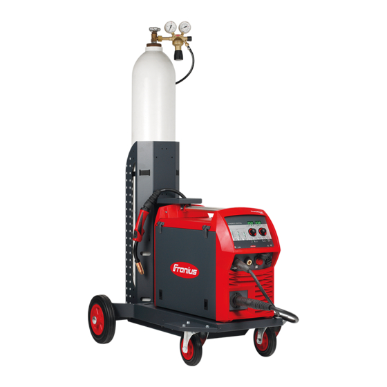
General Device concept The TransSteel (TSt) 3500 and TSt 5000 power sources are completely digitised, mi- croprocessor-controlled inverter power sources. The modular design and potential for sys- tem add-ons ensure a high degree of flexi- bility. The devices are designed for the welding of steel. -
Page 20: Warning Notices On The Device
The TSt 3500/5000 power sources are designed for: Machine and equipment construction Steelwork Plant and container construction Shipyards and the offshore industry Metal and gantry construction Rolling stock construction Warning notices Warning notices and safety symbols are affixed to the power source. These warning notic- on the device es and safety symbols must not be removed or painted over. - Page 21 Safety symbols on the rating plate Welding is dangerous. The following Do not use the functions described here basic requirements must be met: until you have thoroughly read and un- Welders must be sufficiently quali- derstood the following documents: fied these operating instructions Suitable protective equipment all the operating instructions for the...
-
Page 22: System Components
System components General The power sources can be operated with various system components and options. This makes it possible to optimise procedures and to simplify machine handling and operation, as necessitated by the particular field of application in which the power source is to be used. -
Page 23: Options
Options General The options listed below are available with all power source variants. Machine interface The machine interface connects the power source to the machine control. The following signals can be transmitted across the machine interface: Signal input: Start of welding / end of welding Signal input for a floating contact (sensor, relay, etc.) between pin X1:1 and pin X1:2 The machine control signal input is processed by the power source in the same way as a welding torch signal input. -
Page 24: Vrd: Safety Function
Technical data 36 V 150 W A, max VRD: safety func- A Voltage Reduction Device (VRD) is an optional safety device for reducing the voltage. It tion is recommended for environments in which the risk of an electric shock or electrical acci- dent is increased considerably during arc welding: Due to a low human body resistance of the welder If the welder is exposed to a clear risk of touching the workpiece or other parts of the... - Page 25 In MMA welding mode: Within 0.3 seconds of end of welding: VRD is active again The output voltage is limited to 35 V once more...
-
Page 27: Control Elements And Connections
Control elements and connections... -
Page 29: Description Of The Control Panels
Description of the control panels General The functions on the control panels are all arranged in a logical way. The various welding parameters can easily be selected using buttons and can just as easily be altered using buttons or the adjusting dial displayed on the digital display during welding The synergic function ensures that all other welding parameters are adjusted whenever an individual parameter is changed. -
Page 30: Remote" Control Panel
“Remote” control panel General The "Remote" control panel is fitted as a standard part of the power source. The power source is operated from the control panel on the wire-feed unit. The "Remote" power source can be operated via the following system add-ons: Remote control units Wire-feed unit Welding torch... -
Page 31: Connections, Switches And Mechanical Components
Connections, switches and mechanical components TSt 3500/5000 power source (1) (1) TSt 3500/5000 power source Function (-) - Current socket with bayonet latch used to connect the grounding (earthing) cable when MIG/MAG welding to connect the electrode cable or grounding (earthing) cable when MMA welding (depending on the type of electrode used) Mains switch for switching the power source on and off... -
Page 33: Installation And Commissioning
Installation and commissioning... -
Page 35: Minimum Equipment Needed For Welding Task
Minimum equipment needed for welding task General Depending on which welding process you intend to use, a certain minimum equipment lev- el will be needed in order to work with the power source. The welding processes and the minimum equipment levels required for the welding task are then described. -
Page 36: Before Installation And Commissioning
Before installation and commissioning Safety WARNING! Operating the equipment incorrectly can cause serious injury and damage. ► Do not use the functions described here until you have read and completely under- stood these Operating Instructions. ► Do not use the functions described here until you have fully read and understood all of the Operating Instructions for the system components, in particular the safety rules. -
Page 37: Mains Connection
The venting duct is a very important safety feature. When choosing the installation location, ensure that the cooling air can enter and exit unhindered through the air ducts on the front and back of the device. Electroconductive metallic dust (e.g. from grinding work) must not be allowed to get sucked into the device. -
Page 38: Connecting The Mains Cable
Connecting the mains cable General If no mains cable is connected, a mains cable that conforms to the requisite connection voltage must be fitted before commissioning. A strain-relief device for the following cable cross-sections is installed on the power source: Power source Cable cross-section Canada/US... -
Page 39: Fitting The Europe Strain-Relief Device
An illustration of the mains cable connection can be found in the following sections: "Fitting the strain-relief device" or "Fitting the strain-relief device for Canada / US". To connect the mains cable, proceed as follows: Remove the side panel from the device Push the mains cable in far enough to make it possible to connect the PE conductor and the phase conductors to the block terminal properly. -
Page 40: Fitting The Strain-Relief Device For Canada / Us And Tst 5000 Mv Europe
IMPORTANT! Tie the phase conductors near the block terminals using cable ties. Fitting the strain- relief device for Canada / US and TSt 5000 MV Eu- rope 3,5 Nm... - Page 41 IMPORTANT! Tie the phase conductors near the luster terminal using cable ties.
-
Page 42: Generator-Powered Operation
Generator-powered operation Generator-pow- The power source is generator-compatible. ered operation The maximum apparent power S of the power source must be known in order to select 1max the correct generator output. The maximum apparent power S of the power source is calculated as follows: 1max 3-phase devices: S x √3... -
Page 43: Start-Up
Start-up General Commissioning a power source is described by reference to a manual water-cooled MIG/ MAG application. Information on The steps and activities described below include references to various system compo- system compo- nents, including: nents Trolleys Cooling units Wire-feed unit holders Wire-feed units Interconnecting hosepacks Welding torches, etc. -
Page 44: Strain-Relief Device
Strain-relief de- vice... -
Page 45: Connecting The Interconnecting Hosepack
Connecting the IMPORTANT! interconnecting Gas-cooled systems are not fitted with a cooling device. hosepack The water connections therefore do not need to be connected for gas-cooled systems. Connecting the WARNING! gas cylinder If gas cylinders topple over, there is a risk of very serious injury and damage. When using gas cylinders ►... -
Page 46: Creating A Grounding (Earthing) Connection, Connecting The Welding Torch
Creating a grounding (earth- ing) connection, connecting the welding torch Laying the hose- packs correctly Other activities Carry out the following steps in accordance with the wire-feed unit operating instructions: Insert the feed rollers in the wire-feed unit Place the wirespool or basket-type spool and basket spool adapter in the wire-feed unit Feed in the wire electrode Set the contact pressure... -
Page 47: Troubleshooting And Maintenance
Troubleshooting and maintenance... -
Page 49: Troubleshooting
Troubleshooting General The power sources are equipped with an intelligent safety system. This means that it has been possible to dispense with melting-type fuses entirely. Melting-type fuses therefore no longer need to be replaced. After a possible malfunction has been remedied, the power source is ready for use again. - Page 50 Power source has no function Mains switch is on, but indicators are not lit up Cause: There is a break in the mains lead; the mains plug is not plugged in Remedy: Check the mains lead, ensure that the mains plug is plugged in Cause: Mains socket or mains plug faulty Remedy:...
- Page 51 No protective gas shield All other functions are OK Cause: Gas cylinder is empty Remedy: Change the gas cylinder Cause: The gas pressure regulator is faulty Remedy: Replace the gas pressure regulator Cause: Gas hose is not fitted or is damaged Remedy: Fit or change the gas hose Cause:...
-
Page 52: Care, Maintenance And Disposal
Care, maintenance and disposal General Under normal operating conditions, the welding system requires only a minimum of care and maintenance. However, it is vital to observe some important points to ensure the weld- ing system remains in a usable condition for many years. Safety WARNING! An electric shock can be fatal. -
Page 53: Disposal
If a lot of dust has accumulated, clean the cooling air ducts. Disposal Dispose of in accordance with the applicable national and local regulations. -
Page 54: Technical Data
Technical data Special voltages For devices designed for special voltages, the technical data on the rating plate applies. For all machines with a permitted mains voltage of up to 460 V: The standard mains plug allows the user to operate with a mains voltage of up to 400 V. For mains voltages up to 460 V fit a mains plug permitted for such use or install the mains supply directly. -
Page 55: Tst 5000
Mains voltage tolerance -10 / +15 % Grid frequency 50/60 Hz Cos phi (1) 0.99 Max. permitted mains impedance Z at PCC 77 mOhm Recommended earth-leakage circuit breaker Type B Welding current range (I MIG/MAG 10 - 350 A Rod electrode 10 - 350 A Welding current at 10 min / 40 °C (104 °F) -
Page 56: Tst 3500 Mv
Welding current range (I MIG/MAG 10 - 500 A Rod electrode 10 - 500 A Welding current at 10 min / 40 °C (104 °F) 40 % 60 % 100 % 500 A 420 A 360 A Output voltage range according to standard characteristic (U MIG/MAG 14.3 - 39 V Rod electrode... -
Page 57: Tst 5000 Mv
MIG/MAG 10 - 350 A Rod electrode 10 - 350 A Welding current at 10 min / 40 °C (104 °F) 40 % 60 % 100 % : 200 - 460 V 350 A 300 A 250 A Output voltage range according to standard characteristic (U MIG/MAG 14.5 - 31.5 V Rod electrode... - Page 58 MIG/MAG 10 - 500 A Rod electrode 10 - 500 A Welding current at 10 min / 40 °C (104 °F) 35 % 60 % 100 % : 200 V 500 A 420 A 360 A Welding current at 10 min / 40 °C (104 °F) 40 % 60 % 100 %...
- Page 60 FRONIUS INTERNATIONAL GMBH Froniusstraße 1 A-4643 Pettenbach AUSTRIA contact@fronius.com www.fronius.com Under www.fronius.com/contact you will find the addresses of all Fronius Sales & Service Partners and locations.
Need help?
Do you have a question about the TransSteel 3500 and is the answer not in the manual?
Questions and answers