
Related Manuals for Fronius TRANS STEEL 3500 C0MPACT


Summary of Contents for Fronius TRANS STEEL 3500 C0MPACT
- Page 1 TÄYDELLISTÄ HITSAUSTA TRANS STEEL 3500 C0MPACT / Operating Instructions / Spare Parts List v.01/2012 ENG...
- Page 3 Thank you for the trust you have placed in our company and congratulations on buying this high-quality Fronius product. These instructions will help you familiarise yourself with the product. Reading the instructions carefully will enable you to learn about the many different features it has to offer.
-
Page 5: Table Of Contents
Contents Safety rules ..............................Explanation of safety symbols ......................General ..............................Intended purpose ..........................Environmental conditions........................Obligations of the operator........................Obligations of personnel ........................Mains connection ..........................Protecting yourself and others ......................Danger from toxic gases and vapours ....................Danger from flying sparks ........................Risks from mains current and welding current.................. - Page 6 Safety..............................Utilisation for intended purpose only..................... Setup regulations ..........................Mains connection ..........................Connecting the mains cable........................General ..............................Stipulated mains cables and strain-relief devices ................. Connecting the mains cable........................Fit the strain-relief device........................Fit the Canada/US strain-relief device ....................System components ..........................Information on system components ......................
- Page 7 Corrections during welding ........................HotStart function ........................... Anti-stick function..........................Saving and retrieving operating points....................... General ..............................Saving operating points ........................Retrieving operating points ........................Deleting operating points ........................Retrieving operating points on the up/down welding torch ..............Setup settings Setup menu..............................General remarks ...........................
-
Page 9: Safety Rules
Safety rules Explanation of DANGER! indicates immediate and real danger. If it is not avoided, death or se- safety symbols rious injury will result. WARNING! indicates a potentially dangerous situation. Death or serious injury may result if appropriate precautions are not taken. CAUTION! indicates a situation where damage or injury could occur. -
Page 10: Intended Purpose
Intended purpose The device is to be used exclusively for its intended purpose. The device is intended for the welding process described on the rating plate only. Any use above and beyond this purpose is deemed improper. The manufac- turer shall not be liable for any damage resulting from such improper use. Utilisation in accordance with the "intended purpose"... -
Page 11: Obligations Of Personnel
Obligations of Before using the device, all persons instructed to do so undertake: personnel to observe the basic instructions regarding safety at work and accident prevention to read these operating instructions, especially the "Safety rules" section and sign to confirm that they have understood them and will follow them. Before leaving the work area, ensure that people or property cannot come to any harm in your absence. -
Page 12: Danger From Toxic Gases And Vapours
protect eyes and face from UV rays, heat and sparks using a protective visor and regulation filter. wear regulation protective goggles with side protection behind the safety visor. wear stout footwear that provides insulation even in wet conditions. protect the hands with suitable gloves (electrically insulated and providing protection against heat). -
Page 13: Danger From Flying Sparks
Danger from fly- Flying sparks may cause fires or explosions. ing sparks Never weld close to flammable materials. Flammable materials must be at least 11 metres (35 ft) away from the arc, or alternatively covered with an approved cover. A suitable, tested fire extinguisher must be available and ready for use. Sparks and pieces of hot metal may also get into adjacent areas through small gaps or openings. -
Page 14: Meandering Welding Currents
Arrange for the mains and device supply to be checked regularly by a qualified electrician to ensure the PE conductor is functioning properly. The device must only be operated on a mains supply with a PE conductor and a socket with an earth contact. If the device is operated on a mains without a PE conductor and in a socket without an earth contact, this will be deemed gross negligence. -
Page 15: Emc Device Classifications
EMC device clas- Devices with emission class A: sifications are only designed for use in an industrial setting can cause conducted and emitted interference in other areas. Devices with emission class B: satisfy the emissions criteria for residential and industrial areas. This also applies to residential areas in which power is supplied from the public low-voltage grid. -
Page 16: Specific Danger Points
Specific danger Keep hands, hair, clothing and tools away from moving parts. For example: points Fans Cogs Rollers Shafts Wirespools and welding wires Do not reach into the rotating cogs of the wire drive or into rotating drive com- ponents. Covers and side panels may only be opened/removed while maintenance or repair work is being carried out. -
Page 17: Danger From Shielding Gas Cylinders
If the wire-feed unit is attached to a crane holder during welding, always use a suitable, insulated wire-feed unit holder (MIG/MAG and TIG devices). If the device has a carrying strap or handle, this is intended solely for carrying by hand. The carrying strap is not to be used if transporting with a crane, fork- lift or other mechanical hoist. -
Page 18: Safety Measures In Normal Operation
Use internal directives and checks to ensure that the workplace environment is always clean and clearly laid out. Only set up and operate the device in accordance with the degree of protec- tion shown on the rating plate. When setting up the device, ensure there is a gap of 0.5 m (1 ft. 7.69 in.) all round so that cooling air can enter and exit unhindered. -
Page 19: Maintenance And Repair
Any safety devices that are not functioning properly must be repaired before switching on the device. Never bypass or disable protection devices. Before switching on the device, ensure that no one is likely to be endangered. Check the device at least once a week for obvious damage and proper functioning of safety devices. -
Page 20: Safety Inspection
Safety inspection The manufacturer recommends that a safety inspection of the device is per- formed at least once every 12 months. The manufacturer recommends that the power source be calibrated during the same 12-month period. A safety inspection should be carried out by a qualified electrician after any changes are made after any additional parts are installed, or after any conversions after repair, care and maintenance has been carried out... -
Page 21: Copyright
Copyright Copyright of these operating instructions remains with the manufacturer. The text and illustrations are all technically correct at the time of printing. We reserve the right to make changes. The contents of the operating instructions shall not provide the basis for any claims whatsoever on the part of the pur- chaser. -
Page 23: General Information
General information... -
Page 25: General
General Device concept The TransSteel (TSt) 3500c power sources are completely digitised, microprocessor- controlled inverter power sources. The modular design and potential for sys- tem add-ons ensure a high degree of flexi- bility. The devices are designed for the welding of steel. All devices are suitable for: MIG/MAG welding Manual metal arc welding... - Page 26 40,0006,3035 inside Safety symbols on the rating plate Welding is dangerous. The following Do not use the functions described here basic requirements must be met: until you have thoroughly read and un- Welders must be sufficiently quali- derstood the following documents: fied these operating instructions Suitable protective equipment...
-
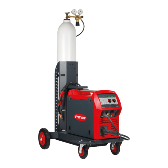
Page 27: System Components
System components General The power sources can be operated with various system components and options. This makes it possible to optimise procedures and to simplify machine handling and operation, as necessitated by the particular field of application in which the power source is to be used. -
Page 29: Control Elements And Connections
Control elements and connections... -
Page 31: Description Of The Control Panel
Description of the control panel General The functions on the control panel are all arranged in a logical way. The individual param- eters required for welding can be selected easily using buttons altered using buttons or the adjusting dial displayed on the digital display during welding The synergic function ensures that all other welding parameters are adjusted whenever an individual parameter is changed. -
Page 32: Synergic Control Panel
Synergic control panel General The power source uses the Synergic control panel and certain general items of data, such as sheet thickness, filler metal, wire diameter and shielding gas, to calculate the best weld- ing parameters. As a result, stored knowledge is available at all times. All the parameters can be adjusted manually. - Page 33 displayed. Dynamic for influencing the short-circuiting dynamic at the moment of droplet transfer - ... harder, more stable arc 0 ... neutral arc + ... soft, low-spatter arc The relevant symbol lights up when a welding parameter is selected. *) In the MIG/MAG standard synergic welding process, if one of these parameters is selected then the synergic function ensures that all other parameters, including the welding voltage parameter, are adjusted automatically.
-
Page 34: Service Parameters
"Process" button for selecting the welding process MANUAL - MIG/MAG standard manual welding SYNERGIC - MIG/MAG standard synergic welding STICK - MMA welding "Mode" button for selecting the mode 2 T - 2-step mode 4 T - 4-step mode S 4 T - Special 4-step mode "Protective gas shield"... - Page 35 Select the required setup parameter using the "Mode" and "Proc- ess" buttons or the left adjusting dial Available parameters Explanation Example: Firmware version 1.00 | 4.21 Example: Welding program configuration 2 | 491 Example: Number of the currently selected welding program 2 | 290 Example: Motor current for wire drive in A...
-
Page 36: Connections, Switches And Mechanical Components
Connections, switches and mechanical components Front and rear (3) (4) (5) Function Welding torch connection for connecting the welding torch (-) - Current socket with bayonet latch used for connecting the grounding (earthing) cable during MIG/MAG welding connecting the electrode cable or grounding (earthing) cable during MMA welding (depending on the type of electrode used) (+) - Current socket with bayonet latch used for... - Page 37 speed. Push button upwards: to set the required gas flow rate at the pressure regulator. Tap button once: shielding gas flows out Tap button again: shielding gas flow stops If the "Gas test" button is not tapped again, the shielding gas flow will stop after 30 Air filter Shielding gas connection Page...
-
Page 39: Installation And Commissioning
Installation and commissioning... -
Page 41: Minimum Equipment Needed For Welding Task
Minimum equipment needed for welding task General Depending on which welding process you intend to use, a certain minimum equipment lev- el will be needed in order to work with the power source. The welding processes and the minimum equipment levels required for the welding task are then described. -
Page 42: Before Installation And Commissioning
Before installation and commissioning Safety WARNING! Operating the equipment incorrectly can cause serious injury and damage. Do not use the functions described until you have thoroughly read and understood the following documents: these operating instructions all the operating instructions for the system components, especially the safe- ty rules WARNING! An electric shock can be fatal. - Page 43 NOTE! Inadequately dimensioned electrical installations can cause serious dam- age. The incoming mains lead and its fuse must be dimensioned to suit the local power supply. The technical data shown on the rating plate applies.
-
Page 44: Connecting The Mains Cable
Connecting the mains cable General A strain-relief device for the following cable cross-sections is fitted to the power source: Power source Cable cross-section Canada/US Europe TSt 3500c AWG 12 *) 4G2.5 Canada/US cable type: extra-hard usage Strain-relief devices for other cable cross-sections must be designed accordingly. Stipulated mains Power source Mains voltage... -
Page 45: Fit The Strain-Relief Device
Fit the strain-re- lief device IMPORTANT! Tie the phase conductors near the luster terminal using cable ties. Fit the Canada/US strain-relief de- vice... - Page 46 IMPORTANT! Tie the phase conductors near the luster terminal using cable ties.
-
Page 47: System Components
System components Information on The steps and activities described below include references to various system compo- system compo- nents, including: nents Trolleys Cooling units Welding torches, etc. For more detailed information about installing and connecting the system components, please refer to the appropriate operating instructions. Fitting the system WARNING! Work that is carried out incorrectly can cause serious injury and dam- components... -
Page 48: Connect The Gas Cylinder
Connect the gas cylinder Connect the gas WARNING! If gas cylinders topple over, there is a risk of very serious injury and cylinder damage. When using gas cylinders: Place them on a solid, level surface in such a way that they remain stable Secure the gas cylinders to prevent them from falling over Fit the VR holder option Follow the gas cylinder manufacturer's safety rules. -
Page 49: Connecting The Welding Torch And Establishing A Ground (Earth) Connection
Connecting the welding torch and establishing a ground (earth) connection Safety NOTE! When connecting the welding torch, check that all connections are connected properly all cables, leads and hosepacks are undamaged and correctly insulated. Connecting MIG/ MAG manual welding torches Establishing a ground (earth) connection... -
Page 50: Inserting/Replacing Feed Rollers
Inserting/replacing feed rollers General In order to achieve optimum wire electrode feed, the feed rollers must be suitable for the diameter and alloy of the wire being welded. IMPORTANT! Only use feed rollers that match the wire electrode. An overview of the feed rollers available and their possible areas of use can be found in the spare parts lists. -
Page 51: Inserting The Wirespool, Inserting The Basket-Type Spool
Inserting the wirespool, inserting the basket-type spool Safety CAUTION! Risk of injury from springiness of spooled wire electrode. When insert- ing the wirespool/basket-type spool, hold the end of the wire electrode firmly to avoid injuries caused by the wire electrode springing back. CAUTION! Risk of injury from falling wirespool / basket-type spool. - Page 52 CAUTION! Risk of injury from falling basket-type spool. Place the basket-type spool on the adapter provided in such a way that the bars on the spool are inside the adapter guideways. CAUTION! Risk of injury and impaired performance if the basket-type spool top- ples over because the locking ring has been placed the wrong way round.
-
Page 53: Feeding In The Wire Electrode
Feeding in the wire electrode Feed in the wire CAUTION! Risk of injury from springiness of spooled wire electrode. When insert- electrode ing the wire electrode into the 4-roller drive, hold the end of the wire electrode firmly to avoid injuries caused by the wire springing back. CAUTION! Risk of damage to the welding torch from sharp end of wire electrode. -
Page 54: Set The Contact Pressure
Set the "Ito" parameter to "Off" in the set-up menu CAUTION! Risk of injury and damage from electric shock and from the wire elec- trode emerging from the torch. When pressing the torch trigger: keep the welding torch away from your face and body do not point the welding torch at people make sure that the wire electrode does not touch any conductive or earthed (grounded) parts, such as the housing, etc. - Page 55 Contact pressure standard values U-grooved rollers Steel 4 - 5 CrNi 4 - 5 Tubular cored electrodes 2 - 3...
-
Page 56: Adjust The Brake
Adjust the brake General NOTE! After releasing the torch trigger the wirespool must stop unreeling. If it continues unreeling, readjust the brake. Adjusting the brake STOP STOP... -
Page 57: Design Of The Brake
Design of the WARNING! Fitting the equipment brake incorrectly can cause serious inju- ry and damage. Do not dismantle the brake. Maintenance and servicing of brakes is to be carried out by trained, qualified personnel only. The brake is only available as a complete unit. -
Page 58: Start-Up
Start-up General WARNING! Operating the equipment incorrectly can cause serious injury and damage. Do not use the functions described until you have thoroughly read and understood the following documents: these operating instructions all the operating instructions for the system components, especially the safe- ty rules The device is started up by pressing the torch trigger (for manual applications). -
Page 59: Welding
Welding... -
Page 61: Power Limitation
Power limitation Safety function "Power limitation" is a safety function for MIG/MAG welding. This means that the power source can be operated at the power limit whilst maintaining process safety. Wire feed speed is a determining parameter for welding power. If it is too high, the arc gets smaller and smaller and may be extinguished. -
Page 62: Mig/Mag Modes
MIG/MAG modes General WARNING! Operating the equipment incorrectly can cause serious injury and damage. Do not use the functions described until you have thoroughly read and understood the following documents: these operating instructions all the operating instructions for the system components, especially the safe- ty rules For details of the meaning, settings, setting range and units of the available welding pa- rameters (e.g. -
Page 63: Special 2-Step Mode
Special 2-step "Special 2-step mode" is ideal for welding in the upper power range. In special 2-step mode mode, the arc starts at a low power, which makes it easier to stabilise. Special 4-step "Special 4-step mode" is particularly suitable for welding in higher power ranges. In special mode 4-step mode, the arc starts at a low power, which makes it easier to stabilise. -
Page 65: Mig/Mag Welding
MIG/MAG welding Safety WARNING! Operating the equipment incorrectly can cause serious injury and damage. Do not use the functions described until you have thoroughly read and understood the following documents: these operating instructions all the operating instructions for the system components, especially the safe- ty rules WARNING! An electric shock can be fatal. -
Page 66: Mig/Mag Standard Synergic Welding
MIG/MAG standard Synergic welding MIG/MAG stand- Press the "Material" button to select the filler metal to be used. ard synergic welding Assignment of the SP position depends on the welding database used for the power source. Press the "Wire diameter" button to select the diameter of the wire electrode to be used. -
Page 67: Corrections During Welding
If there is a "Feeder inching"/"Gas test" button: Press the "Feeder inching" / "Gas test" button upwards and release Turn the adjusting screw on the underside of the pressure regulator until the pres- sure gauge shows the required gas flow rate Press the "Feeder inching"... -
Page 68: Mig/Mag Standard Manual Welding
MIG/MAG standard manual welding General remarks The MIG/MAG standard manual welding process is a MIG/MAG welding process with no Synergic function. Changing one parameter does not result in any automatic adjustments to the other param- eters. All of the variable parameters must therefore be adjusted individually, as dictated by the welding process in question. -
Page 69: Corrections During Welding
Set the shielding gas flow rate: If there is a "Feeder inching"/"Gas test" button: Press the "Feeder inching" / "Gas test" button upwards and release Turn the adjusting screw on the underside of the pressure regulator until the pres- sure gauge shows the required gas flow rate Press the "Feeder inching"... -
Page 70: Mma Welding
MMA welding Safety WARNING! Operating the equipment incorrectly can cause serious injury and damage. Do not use the functions described until you have thoroughly read and understood the following documents: these operating instructions all the operating instructions for the system components, especially the safe- ty rules WARNING! An electric shock can be fatal. -
Page 71: Corrections During Welding
All welding parameter set values remain stored until the next time they are changed. This applies even if the power source is switched off and on again in the meantime. Start welding To display the actual welding current during welding: Press the "Parameter selection"... - Page 72 Electrode burn-out is prevented by activating the anti-stick function. If the rod electrode be- gins to stick, the power source immediately switches the welding current off. After the rod electrode has been detached from the workpiece, the welding operation can be continued without difficulty.
-
Page 73: Saving And Retrieving Operating Points
Saving and retrieving operating points General The "Save" buttons allow up to 5 operating points to be saved. Every operating point matches the settings on the control panel. IMPORTANT! Setup parameters are not saved at this time. Saving operating Press and hold one of the "Save" buttons to save the current settings on the control points panel, e.g.: The left indicator displays "Pro". -
Page 74: Retrieving Operating Points On The Up/Down Welding Torch
After a short time, the left indicator switches to the original value, e.g.: Keep the "Save" button held down The left display shows "CLr". After a while, both displays show "---" Release the "Save" button Retrieving operat- One of the "Save" buttons on the control panel must be pressed to retrieve the saved set- ing points on the tings using the up/down welding torch. - Page 75 Number 4 Number 5...
-
Page 77: Setup Settings
Setup settings... -
Page 79: Setup Menu
Setup menu General remarks The Setup menu provides simple access to expert knowledge in the power source and to additional functions. The Setup menu can be used to make simple adjustments of the pa- rameters to suit the various job settings. Setting the set-up Setting the set-up parameters is described here with reference to the "MIG/MAG standard parameters... -
Page 80: Set-Up Parameters For Mig/Mag Standard Manual Welding
Set-up parame- "Min." and "max." are used for setting ranges that differ according to power source, welding ters for MIG/MAG program, etc. standard manual welding Gas pre-flow time Unit: s Setting range: 0 - 9.9 Factory setting: 0.1 Gas post-flow time Unit: s Setting range: 0 - 9.9 Factory setting: 0.1... - Page 81 - when "PrG" appears on the digital display, the power source has been reset IMPORTANT! When the power source is reset, all the personal settings in the set- up menu are lost. Operating points that were saved using the "Save" buttons are retained when the power source is reset.
-
Page 82: Set-Up Parameters For Mig/Mag Standard Synergic Welding
Set-up parame- "Min." and "max." are used for setting ranges that differ according to power source, welding ters for MIG/MAG program, etc. standard syner- gic welding Gas pre-flow time Unit: s Setting range: 0 - 9.9 Factory setting: 0.1 Gas post-flow time Unit: s Setting range: 0 - 9.9 Factory setting: 0.1... - Page 83 Factory setting: Aut Ignition time-out - length of wire that is fed before the safety cut-out trips Unit: mm (in.) Setting range: Off, 5 - 100 (Off, 0.2 - 3.94) Factory setting: Off NOTE! The "Ignition time-out" function (ito) is a safety function. The length of wire that is fed before the safety cut-out trips may differ from the pre-set wire length, particularly when the wire is being fed at fast wire feed speeds.
-
Page 84: Set-Up Parameters For Mma Welding
Set-up parame- IMPORTANT! If you reset the power source using the FAC factory set-up parameter, the ters for MMA hot-current time (Hti) and HotStart current (HCU) set-up parameters are also reset. welding HotStart current Unit: % Setting range: 100 - 200 Factory setting: 150 Hot-current time Unit: s... -
Page 85: Setup Menu - Level 2
Setup menu - Level 2 Restrictions In conjunction with the Level 2 set-up menu, the following restrictions occur: The Level 2 set-up menu cannot be selected: during welding if the "Gas test" function is active if the "Wire threading" function is active if the "Wire withdrawal"... -
Page 86: Welding Parameters For Mig/Mag Welding In The Level 2 Set-Up Menu
change the value of the set-up parameter using the "Dynamic" button or the right adjusting dial Exiting the Level 2 set-up menu Press and hold the "Mode" button Press the "Process" button Release the "Mode" and "Process" buttons Exiting the set-up menu Press and hold the "Mode"... - Page 87 the cooling unit will not cut out until the end of this pre-set time. Unit: s Setting range: 5 - 25 Factory setting: 10 IMPORTANT! Each time the power source is switched on, the cooling unit carries out a test run for 180 seconds. Setting - country-specific setting (standard/USA) ...
-
Page 88: Measuring Welding Circuit Resistance R
Measuring welding circuit resistance r General Measuring the welding circuit resistance "r" makes it possible to have a constant welding result at all times, even with hosepacks of different lengths. The welding voltage at the arc is then always precisely regulated, regardless of the length and cross-sectional area of the hosepack. -
Page 89: Displaying Welding Circuit Inductivity L
Displaying welding circuit inductivity L General Laying of the hosepacks has a significant effect on welding circuit inductivity and therefore affects the welding process. It is important to lay the hosepacks correctly in order to obtain the best possible welding result. Displaying weld- The setup parameter "L"... -
Page 91: Troubleshooting And Maintenance
Troubleshooting and maintenance... -
Page 93: Troubleshooting
Troubleshooting General The devices are equipped with an intelligent safety system. This means that to a large ex- tent it has been possible to dispense with melting-type fuses. Melting-type fuses therefore no longer need to be replaced. After a possible malfunction has been remedied, the device is ready for use again. - Page 94 Nothing happens when the torch trigger is pressed Power source mains switch is on, power source ON indication is lit up on the power source, indications on wire-feed unit are not lit up Cause: The interconnecting hosepack is faulty or not connected properly Remedy: Check interconnecting hosepack No welding current...
- Page 95 Irregular wire feed speed Cause: Braking force has been set too high Remedy: Loosen the brake Cause: Hole in the contact tube is too narrow Remedy: Use a suitable contact tube Cause: Wire feed liner in the welding torch is faulty Remedy: Check the wire feed liner for kinks, dirt, etc.
-
Page 96: Displayed Service Codes
Poor weld properties Cause: Incorrect welding parameters Remedy: Check the settings Cause: Poor grounding (earthing) connection Remedy: Ensure good contact to workpiece Cause: Inadequate protective gas shield, or none at all Remedy: Check the pressure regulator, gas hose, gas solenoid valve, torch gas con- nection, etc. - Page 97 ELn | 12 Cause: Different control panels for selecting materials are in the system Remedy: Connect similar control panels to select materials ELn | 13 Cause: Illegal change of welding process during welding Remedy: During welding do not carry out any illegal change of the welding process, re- set error message by pressing any button Err | PE Cause:...
- Page 98 to1 | xxx Note: xxx stands for a temperature value Cause: Overtemperature on the booster located in the power source Remedy: Allow power source to cool down, check air filter and clean if necessary, check that fan is on to2 | xxx Note: xxx stands for a temperature value Cause: Overtemperature in the secondary circuit of the power source...
- Page 99 tu2 | xxx Remark: xxx stands for a temperature value Cause: Undertemperature in the power source secondary circuit Remedy: Place power source in a heated room and allow to warm up tu3 | xxx Remark: xxx stands for a temperature value Cause: Undertemperature in the wire-feed unit motor Remedy:...
- Page 100 no | IGn Cause: "Ignition time out" function is active; no current started flowing before the length of wire specified in the set-up menu had been fed. The power source safety cut-out has tripped. Remedy: Shorten the wire end; press the torch trigger again; clean the surface of the workpiece;...
-
Page 101: Care, Maintenance And Disposal
Care, maintenance and disposal General Under normal operating conditions the welding system requires only a minimum of care and maintenance. However, it is vital to observe some important points to ensure the weld- ing system remains in a usable condition for many years. Safety WARNING! An electric shock can be fatal. -
Page 102: Technical Data
36 kg (79.37 lb.) Overvoltage category Pollution level according to IEC60664 Maximum shielding gas pressure 5 bar 72.49 psi. Coolant Original Fronius Gear ratio 16 : 1 Wire feed speed 1 - 25 m/min 39.37 - 984.25 ipm. Wire drive... - Page 103 Wirespool diameter max. 300 mm max. 11.81 in. Wirespool weight max. 19 kg max. 41.89 in. 1) connected to public grids with 230 / 400 V and 50 Hz 2) PCC = interface to public grid 3) d.c. = duty cycle...
-
Page 104: Quick Reference
Quick reference... -
Page 107: Annex
Annex... -
Page 108: Spare Parts List: Transsteel 3500C
Spare parts list: TransSteel 3500c... - Page 109 1. 2 2. 2 178 936-A...
- Page 111 Motorplatte Alu 4R s 44,0001,1405 - U 0,8 44,0001,1406 - U 0,9-1,0 44,0001,1407 - U 1,2 44,0001,1408 - U 1,4-1,6 44,0001,1431 - R 1,2 44,0001,1432 - R 1,4 44,0001,1433 - R 1,6 42,0405,1095 t o r 42,0407,0667 t o r 44,0350,3201 42,0404,0384 44,0001,1413...
- Page 112 Maahantuonti ja myynti: Pronius Oy Keisarinviitta 20 B 33960 Pirkkala +358 (0)44 200 9060 info@pronius.fi www.pronius.fi...
Need help?
Do you have a question about the TRANS STEEL 3500 C0MPACT and is the answer not in the manual?
Questions and answers