Table of Contents
Advertisement
Quick Links
DLP5530Q1EVM Evaluation Module User's Guide
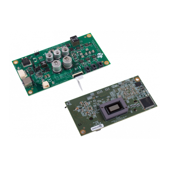
The DLP5530Q1EVM Evaluation Module (EVM) is a complete electronic subsystem designed to control
the DLP5530-Q1 chipset. The DLP5530-Q1 chipset consists of the DLP5530-Q1, the DLPC230-Q1, and
the TPS99000-Q1. When combined with illumination and projection optics, RGB LEDs and a photodiode,
this EVM can be used to develop an automotive grade projector for applications such as augmented
reality head-up display (AR HUD) or interior projection systems.
Except for the DMD, there are no optical elements provided with this EVM. It is expected that this EVM is
procured in order to mount to a custom designed picture generation unit (PGU) or projector.
The DLP5530Q1EVM is not a production design. It is intended for evaluation only.
The DLP5530Q1EVM electronics EVM pairs with 3 different optical module configurations, all available as
standalone EVMs. The different options are listed below in
EVM Part Number
DLP5530PGUQ1EVM
DLP5530PROJQ1EVM
DLP5530PROJTGQ1EVM
DLPU090 – November 2019
Submit Documentation Feedback
Figure 1. The DLP5530Q1EVM
Table 1. Optical Module EVM Descriptions
Typical Application
Head up display
Full color transparent window display
Holographic cluster display
Copyright © 2019, Texas Instruments Incorporated
DLPU090 – November 2019
Table
1.
Key Features
Short throw distance for creating HUD images
on a diffuser screen
Variable throw distance for creating large images
of scalable sizes
Direct green LED for narrow band illumination
of holographic optical elements
DLP5530Q1EVM Evaluation Module User's Guide
User's Guide
1
Advertisement
Table of Contents

Related Manuals for Texas Instruments DLP5530Q1EVM


Summary of Contents for Texas Instruments DLP5530Q1EVM
-
Page 1: The Dlp5530Q1Evm
The DLP5530Q1EVM is not a production design. It is intended for evaluation only. Figure 1. The DLP5530Q1EVM The DLP5530Q1EVM electronics EVM pairs with 3 different optical module configurations, all available as standalone EVMs. The different options are listed below in Table Table 1. -
Page 2: Table Of Contents
Contents ......................User Guide Overview ................What is in the DLP5530Q1EVM EVM ...................... Specifications ........................Quick Start ..................Kit Assembly Instructions ....................Software Installation ....................Powering-Up EVM ............. Connecting EVM to the DLPC230-Q1 Control Program ............. Steps to Reprogram the Onboard Flash Memory ..................... -
Page 3: User Guide Overview
This user's guide presents an overview and general description of the DLP5530Q1EVM and provides first steps for getting started using the EVM. What is in the DLP5530Q1EVM EVM The DLP5530Q1EVM consists of a controller PCB, an illumination driver PCB, cables, and a USB to SPI adapter. 1.1.1... -
Page 4: Controller Pcb Ports
On: Mode 1 or 2 Hold in Boot Off: Do not hold in boot (continue to main application) On: Hold in boot DLP5530Q1EVM Evaluation Module User's Guide DLPU090 – November 2019 Submit Documentation Feedback Copyright © 2019, Texas Instruments Incorporated... - Page 5 SIGNAL NUMBER PROJ_ON Off: Turn off system On: Turn on system On state is toward the outer edge of the board Figure 2 DLPU090 – November 2019 DLP5530Q1EVM Evaluation Module User's Guide Submit Documentation Feedback Copyright © 2019, Texas Instruments Incorporated...
-
Page 6: Dlp5530Q1Evm Illumination Driver Pcb
EVM. Depending on operating conditions, some parts and surfaces of the PCB can be hot. CAUTION Hot surface. Contact may cause burns. Do not touch! Figure 3. DLP5530Q1EVM Illumination Driver PCB The illumination driver PCB contains the ports listed in Table DLP5530Q1EVM Evaluation Module User's Guide DLPU090 –... -
Page 7: Illumination Driver Pcb Ports
Pre-regulated drive voltage (6.5 V or 8 V) Feedback voltage connection Feedback voltage connection Pre-regulator feedback voltage for 6.5-V drive for 8-V drive DLPU090 – November 2019 DLP5530Q1EVM Evaluation Module User's Guide Submit Documentation Feedback Copyright © 2019, Texas Instruments Incorporated... -
Page 8: Evm Cables
User Guide Overview www.ti.com 1.1.3 EVM Cables The DLP5530Q1EVM kit contains the cables and Cheetah USB to SPI adapter listed in Table 7 shown in Figure Figure 4. EVM Cables Table 7. EVM Cables NAME REFERENCE QUANTITY Input Power Cable Cheetah™... - Page 9 Blue Illuminator Power Cable Red Illuminator Power Cable Photodiode Cable Driver to Formatter Controller Power Cable Formatter Controller to Driver Control Flex Micro HDMI Cable DLPU090 – November 2019 DLP5530Q1EVM Evaluation Module User's Guide Submit Documentation Feedback Copyright © 2019, Texas Instruments Incorporated...
-
Page 10: Specifications
IC PANELBUS DVI Controller U501 TFP401AIPZPRQ1 Texas Instruments –40 RCVR 100-HTQFP Illumination CONN PWR JACK PJ-082BH CUI Inc –25 Driver 2.5X5.5MM SOLDER DLP5530Q1EVM Evaluation Module User's Guide DLPU090 – November 2019 Submit Documentation Feedback Copyright © 2019, Texas Instruments Incorporated... -
Page 11: Typical Timing For Supported Source Resolutions
User Guide Overview www.ti.com The controller and illumination driver PCBs have a UL flame rating of 130°C maximum. The DLP5530Q1EVM is not a production design. It is intended for evaluation only. 1.2.3 Input Video Specifications The following input video resolutions are supported on the HDMI and OpenLDI interfaces. These input video resolutions are programmed in the Extended Display Identification Data (EDID) EEPROM for the EVM's HDMI interface allowing a connected computer to read the supported resolutions and timing. -
Page 12: Quick Start
Quick Start www.ti.com Quick Start Use the following instructions to setup the DLP5530Q1EVM and PC. Kit Assembly Instructions A diagram of all connections is shown in Figure 1. Connect the controller to driver control interface flex to the controller PCB (J8) and the illumination driver PCB (J4). -
Page 13: Software Installation
6). Note, the Cheetah must be connected to computer with USB cable for it to show up in the drop down box. Figure 6. Connecting to the DLPC230-Q1 Using the DLPC230-Q1 Automotive Control Program DLPU090 – November 2019 DLP5530Q1EVM Evaluation Module User's Guide Submit Documentation Feedback Copyright © 2019, Texas Instruments Incorporated... -
Page 14: Steps To Reprogram The Onboard Flash Memory 3 Optical Engine Requirements
Note that if the device is in Display mode, it will automatically be switched to Standby during programming. Optical Engine Requirements The DLP5530Q1EVM can be coupled to an optical engine (not included) to implement a head-up display function or an automotive interior projection system. The detailed requirements of the optical engine are beyond the scope of this document, but the optical engine should have separate red, green and blue illuminators. - Page 15 DLPU090 – November 2019 DLP5530Q1EVM Evaluation Module User's Guide Submit Documentation Feedback Copyright © 2019, Texas Instruments Incorporated...
- Page 16 TI products. TI’s provision of these resources does not expand or otherwise alter TI’s applicable warranties or warranty disclaimers for TI products. Mailing Address: Texas Instruments, Post Office Box 655303, Dallas, Texas 75265 Copyright © 2019, Texas Instruments Incorporated...
Need help?
Do you have a question about the DLP5530Q1EVM and is the answer not in the manual?
Questions and answers