Atlas Equipment BP12000X Installation & Operation Manual
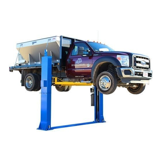
12,000 lb. capacity two-post baseplate lift
Hide thumbs
Also See for BP12000X:
- Installation & operation manual (45 pages) ,
- Installation & operating manual (45 pages)
Table of Contents
Advertisement
Quick Links
Advertisement
Table of Contents

Related Manuals for Atlas Equipment BP12000X


Summary of Contents for Atlas Equipment BP12000X
- Page 1 Model: BP12000X Revised: 05/26/2021...
-
Page 2: Table Of Contents
CONTENTS Product Features and Specifications ..........3 Installation Requirement .............5 Steps of Installation ………………………………………………..……………………………7 Exploded View ................24 Test Run ..................29 Operation Instruction ..............30 Maintenance ................31 Trouble Shooting ..............32 Lift Disposal................32 Parts List ................33 Warranty ................36... -
Page 3: Product Features And Specifications
· Single-point safety release, and dual safety design. · Super-Symmetric arm design with 3-stage front and rear arms. · Adjustable width settings. . Stackable rubber pad with 1.5”, 2.5’’ and 5” extension adaptors. Fig. 1 MODEL BP12000X SPECIFICATIONS Width Minimum Lifting Lifting... - Page 4 Arm Swings for Model 212 Fig. 2...
-
Page 5: Installation Requirement
II. INSTALLATION REQUIREMENT A. TOOLS REQUIRED ✓ Rotary Hammer Drill (Φ19) Carpenter’s Chalk ✓ ✓ Hammer Screw Sets ✓ ✓ Level Bar Tape Measure (7.5m) ✓ ✓ English Spanner (12") Pliers ✓ ✓ Ratchet Spanner With Socket (28 Socket Head Wrench (6 ✓... - Page 6 Equipment storage and installation requirements. The equipment should be stored or installed in a shady, normal temperature, ventilated and dry place. The equipment should be unloaded and transferred by forklift. Fig 4 D. SPECIFICATIONS OF CONCRETE (See Fig. 5). Concrete must adhere to the specifications listed below, failure to do so may result in lift and/or vehicle falling.
-
Page 7: Steps Of Installation
E. POWER SUPPLY 220volt single phase source on a 30amp breaker with minimum of 10 gauge wire running to the power unit. Operating voltage range is 208v-230v. III. STEPS OF INSTALLATION A. Location of Installation Check and ensure the installation location (concrete, layout, space size etc.) is suitable for lift installation. - Page 8 3. Take off the parts from upper and inside the column, then take out the parts box (See Fig. 9). Aluminum serial label Fig. 9 4. Loosen the bolts of the upper package stand, take off the upper column and remove the package stand 5.
- Page 9 Parts in the parts box (84) Fig. 11 6. Open the parts bag and check the parts according to parts bag list (See Fig. 12). Fig.
- Page 10 D. Install Columns Lay down two columns on the installation site parallel, position the powerside column according to the actual installation site. Usually, it is suggested to install powerside column on the front-right side from which vehicles are driven to the lift, then install the top plates (See Fig.13).
- Page 11 D. Position the Columns & Install anchor bolts. Position the columns on the installation lines laid out and loosely install the anchor bolts. Do not tighten the anchor bolts. Check the columns plumbness with a level and adjust with shims if the columns are not vertical. (See Fig. 14). Note: This lift features an adjustable width, please set the width and install the lift according to your needs.
- Page 12 2. Using the prescribed rotary hammer drill, drill all the anchor holes and install the anchor bolts. Then tighten the anchor bolts (See Fig. 16). Note: Torque of Anchors is 150N.m. or 110 Ft lbs. Minimum embedment of anchors is 6”. Fig.
- Page 13 H. Lift the carriages up by hand and make them be locked at the same level (See Fig. 19). Safety device locked at the same level Fig. 19...
- Page 14 I. Install cable According to step E to choose the width distance of your lift (See Fig.14) 1. For overall width of 150 ½” (See Fig.20) Note: Pass through the cable from the hole of the strength plate of one carriage to another carriage.
- Page 15 2. For overall width of 145 3/8” 2.1 Pass through the cable from the bottom to the top of the carriage, the end of cable will pass through the hole of the carriages and be held with two cable nuts. (See Fig.
- Page 16 2.2. Pass through the cable according to the arrow direction (See Fig. 22) Fig. 22...
- Page 17 J. Install cable of safety device (See Fig. 23). Note: Install the safety cable from the offside safety device, pay attention to the pass through direction. Install the safety cable from the offside safety device 2. According to the arrow direction to pass through the cable from offside safety device to power...
- Page 18 K. Install hydraulic power unit and oil hose assy. (See Fig. 24). View A View For columns distance 118 1/8”, use 54 ¾” oil hose. For columns distance 123 ½”, use 59 7/8” oil hose. Fig. 24...
- Page 19 L. Install floor cover (See Fig. 25). Choose different extension cover according to the width distance. NOTE: Installation for 123 ½” columns Use long extension cover to distance: connect the floor cover. Installation for 118 1/8” columns distance: Use short extension cover to connect the floor cover.
- Page 20 Adjust the Moon gear Locking the nuts after the moon gear and arm lock engaged well Fig. 28 2. Install toe guard. Fig. 29 N. Tighten all the oil hose connectors, fill with tank with Hydraulic Oil. To ensure the longevity of all hoses and hydraulic parts use 3-5 gallons of recommended AW32 or AW46 anti-wear hydraulic oil.
- Page 21 O.Install electrical system Connect the power source as required on the data plate of Power Unit. Note: 1. For the safety of operators, the power wiring must be grounded. 1.Connect the two power supply lines (fire wire L and zero wire N) to terminals of AC contactor marked L1, L2 respectively.
-
Page 22: Exploded View
IV. EXPLODED VIEW Model BP12X Car in Fig. 35... - Page 23 a. Exploded view of lifting arm assembly (10207062) Fig 36 Item Part# Description Qty. Item Part# Description Qty. M10*30 hex bolt Outer arm 10206048 11207012A φ10 washer Middle arm 10209039 11217337 φ10 washer Screw M8*12 10209022 10201149 Moon gear Inner arm 11206049 11217836 b.
- Page 24 c. Exploded view of the oil Cylinder (10207010) Fig. 38 Cylinder parts list Item Part# Description Item Part# Description Piston Rod Adjustment Tube 20-1 11207027 20-8 10207029 Cylinder Piston Dust Ring 20-2 11207028 20-9 10217078 Adjustment Tube O-Ring O-Ring 20-3 10206069 20-10 10520058...
- Page 25 d. Exploded view of power unit 220V/60HZ/1Phase Fig. 39 Single-phase 220V, 60Hz manual power unit parts list Item Part# Description Item Part# Description Rubber pad AC connector 81400180 41030055 Start capacitor Cover of Motor 81400130 81400287 Terminal Box AMGO Sticker Running capacitor 81400088 71111171...
- Page 26 e. Illustration of hydraulic valve for hydraulic power unit Relief valve Oil return port Release Oil Out Throttle valve valve Release valve handle Check valve Fig. 40...
-
Page 27: Test Run
V. TEST RUN 1. Adjustment of synchronous cable (See Fig. 41) Use wrench to hold the cable end, meanwhile use ratchet spanner to tighten the cable nuts until the two cables Cable are at the same tension. If the two vehicle carriages do not Synchronize when lifting and lowering, please screw and tighten the cable nut on the lower side carriage. -
Page 28: Operation Instruction
Fig. 43 Hydraulic System VI. OPERATION INSTRUCTIONS Please read the safety tips carefully before operating the lift To lift vehicle 1. Keep work site near the lift clean and clear at all times; 2. Position carriages and lift arms to the lowest position; 3. -
Page 29: Maintenance
3. Open the arms until they are clear of the vehicle; 4. Drive away the vehicle. 5. Turn off the power. Note: In order to extend the service life of the cylinder and seals, raise the lift to top at least once a day VII. -
Page 30: Trouble Shooting
4. Protect the outer surface of the oil cylinder’s piston rod from bumping and scratching, and timely clean up the debris on the oil cylinder dust-ring and the piston rod. VIII.TROUBLE SHOOTING TROUBLE CAUSE REMEDY 1. Button does not work 1. -
Page 31: Parts List
X. PARTS LIST FOR MODEL 212 Item Part# Description Qty. Note 11207001 Floor cover 11207002 Short extension cover 11207003 Long extension cover 11217019 Top pulley 10217020 Bronze bush for pulley 10209012 Hair pin 10209005 Self-locking nut 10209033 Washer 10209043 Hex bolt 11207055 Power side column 81513003/... - Page 32 Item Part# Description Qty. Note 10206036 Hair Pin 10217044 Arm lock 10217045A Spring 11217046B Left arm lock bar 11217046C Right arm lock bar 10209153 Arm lock bar ring 10201010A Chain connector BL646 10207015 Chain BL646 10209038 Hex bolt 11207016 Top plate assy. 11217037 Pin for bottom pulley 11217036...
- Page 33 Item Part# Description Qty. Note Cable 10207022 10209066 Cable nut Safety cable L=7450mm 10206149 10209049 Plastic small pulley 10207023 Oil hose 5/16*3210mm 10209060 90-degree Fitting for power unit 10209004 Rubber ring 10209003 Hex bolt 10207024 90-degree Fitting 11207035 Length fitting L=86mm 10420097 90-degree Fitting 10207026...
-
Page 34: Warranty
X. WARRANTY: This item is warranted for five (5) years on structural components, two (2) years on hydraulic cylinders, and one (1) year on electric or air / hydraulic power units from invoice date. Wear items are covered by a 90 day warranty.
Need help?
Do you have a question about the BP12000X and is the answer not in the manual?
Questions and answers