Table of Contents
Advertisement
Quick Links
Advertisement
Table of Contents

Related Manuals for Atlas Equipment Atlas BP9000X


Summary of Contents for Atlas Equipment Atlas BP9000X
-
Page 2: Table Of Contents
CONTENTS Product Features and Specifications ............ 3 Installation Requirement ..............5 Steps of Installation ................7 Exploded View ................19 Test Run ..................22 Operation Instruction ..............25 Maintenance ................. 25 Trouble Shooting ................26 Parts List ..................27... -
Page 3: Product Features And Specifications
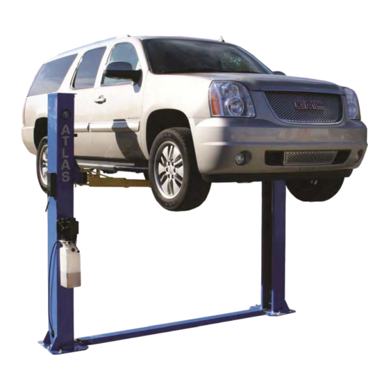
I. FLOORPLATE CHAIN-DRIVE TWO POST LIFT Model BP9000X · Compact design · Dual hydraulic cylinders, designed and made on ANSI standards, utilizing NOK oil seal for cylinder · Self- lubricating UHMW Polyethylene sliders and bronze bushings · Single-point safety release and dual safety design ·... - Page 4 Model BP9000X...
-
Page 5: Installation Requirement
II. INSTALLATION REQUIREMENT A. TOOLS REQUIRED Rotary Hammer Drill (3/4” Drill Bit) Tape Measure Hammer Pliers Level Bar Allen Head Wrench (6 Crescent Wrench (12") Vise Grips Ratchet Spanner With Socket , 13 , 14 , 15... - Page 6 B. CONCRETE SECIFICATIONS (See Fig. 3). Concrete Specifications Must Be Followed. Failure To Do So May Result In Lift and /or Vehicle Falling. 1. Concrete must be a minimum of 4” and without reinforcing steel bars, and must be dried totally before the installation. 2.
-
Page 7: Steps Of Installation
III. STEPS FOR INSTALLATION A. Location of Installation Check the installation location (concrete, layout, space, size etc.) for the lift installation. B. Use a carpenter’s chalk line to establish installation layout of the base plate (See Fig. 4). Fig. 4 Model BP9000X C. - Page 8 2. Unload the lift with a fork lift or hoist, and open the outer packing carefully (See Fig. 6). Shipment Parts list Serial No. Floor cover Parts box Fig. 6 3. Remove the parts from upper and inside the column, then take out the parts box, and check the parts according to the shipment parts list (See Fig.
- Page 9 4. Loosen the screws from the upper package stand, take off the upper column and remove the package stand (See Fig. 8). Fig. 8 5. Open the box of parts and check the parts according to parts box list (See Fig. 9). Fig.
- Page 10 D. Position Power Side Post Lay down the two posts on the installation site parallel, position the Power side post according to the location of the actual installation. Usually, it is suggested to install Power side Post on the front-right side from which vehicles are driven to the lift (See Fig.
- Page 11 2. Push the carriages to the bottom of the columns (See Fig. 13). Fig. 13 F. Position posts (See Fig. 14) Check the posts plumb with level a, and adjust with shims if the posts are not level. 112" (9' 4") Helpful tip for correct post to post width: Set the power side post into its designated position.
- Page 12 G. Install the Anchor Bolts Washer Lock washer 1. Prepare anchor bolts. (See Fig. 14) Fig. 14 2. Use a rotary hammer drill with a ¾” masonry drill bit, and drill all the anchor holes and install the anchor bolts. Tighten the anchor bolts to 100 foot pounds (See Fig.
- Page 13 I. Install Cables (See Fig. 17) The fitting of cable pass through the hole of the carriages and be screwed with two cable nuts. Fig. 17 J. Hydraulic Hose Assembly (See Fig. 18). Fig. 18...
- Page 14 K. Install Hydraulic Power Unit and the Hydraulic Hose (See Fig. 19). Tighten all the hydraulic fittings, and fill the reservoir with hydraulic oil. Note: Before filling the power unit reservoir, make electrical connections to the 220volt power unit and test run it for a few seconds to see if it operates properly. Fill the power unit reservoir with #32 series hydraulic oil;...
- Page 15 L. Install Safety Device and Safety Cable (See Fig. 20). 1. Install the safety cable from the offside lock assembly. NOTE: 2. Pay attention to the connecting direction of the safety cable. View A View B Safety Cable Connecting direction Fig.
- Page 16 M. Assemble Floor Cover and Protective Rubber Guards (See Fig. 21). Protective rubber door guard Floor Cover Fig. 21 N. Install the Lifting Arms and Adjust the Arm Locks 1. Install the Lifting Arms (See Fig. 22). Fig. 22...
- Page 17 2. Lowing the carriages down to the lowest position, then use the wrench to loosen the (See Fig. 23) Loose the nut Fig. 23 3. Adjust the arm lock either back or forth to mesh the gear lock teeth (See Fig. 24). Fig.
- Page 18 O. Install Electrical System Note: Single phase motor wiring (See Fig. 25) 1. Connect the two power supply lines (fire wire L and zero wire N) to terminals on the AC contactor marked L1, L2. 2. Connect the two motor wires to terminals on the AC contactor marked T1, T2. 3.
-
Page 19: Exploded View
Exploded View... - Page 20 Cylinder Exploded View Hydraulic Power Unit Exploded View...
- Page 21 PEAK hydraulic power unit...
-
Page 22: Test Run
V. TEST RUN First Safety Lock 1. Adjust Synchronizing Cables (See Fig. 26) Use a crescent wrench to hold the cable end and Use a ratchet or wrench to tighten the cable nut. Make sure the two cables have the same tension. Cable Nut The two carriages should go up and down at the same time. - Page 23 Lock the left carriage to let the right carriage come The right carriage and down as high as the left arms are higher than the left Fig. 28 2. Adjusting the Safety Cable Raise the carriages to same height and lower on the safety locks, tighten the safety cable and then release the tension a little, and then tighten the cable nuts.
- Page 24 4. Test with load Test run the lift with a load. Run the lift in low position several times, make sure the lift carriages can raise and lower at the same time. The safety locks should engage and release at the same time. Test run the lift to the top and bottom. The above steps may need to be repeated if the lift arms raise or lower at different intervals.
-
Page 25: Operation Instruction
VI. OPERATION INSTRUCTIONS Please read the safety tips carefully before operating the lift To lift vehicle 1. Keep of environment near the lift clean; 2. Position lift arms to the lowest position; 3. Position vehicle between columns evenly; 4. Move arms to the vehicle’s lifting points; Note: The four lift arms must contact the vehicle’s lifting point at the same time. -
Page 26: Trouble Shooting
VII. TROUBLE SHOOTING TROUBLE CAUSE REMEDY 1. Button does not work 1. Replace button 2. Wiring connections are not in good 2.Repair all wiring connections condition Motor does not 3. Motor burned out 3. Repair or replace motor 4. Height Limit Switch is damaged 4.Replace the Limit Switch 5. -
Page 27: Parts List
IX. Parts List For Model BP9000x B. Parts for Model BP9000X Item. Part No. Description Qty. Note 203001 Power Side Post 209011 Plastic Pulley 209010 Snap Ring 209008 Safety Cover 209009 Cup Head Bolt 206006 Washer 206023A Hex Nut 209002 Hydraulic Power Unit 209006 Safety Pin... - Page 28 209023A Teeth 209024 Arm Lock Bar 209025 Hair Pin 209026 Spring 209027 Protective Rubber Set Lifting Arm - Front Right (Drop-in) 201012C Lifting Arm - Front Left (Drop-in) 201013C Lifting Arm - Rear Left (Drop-in) 201014B 203008 Offside Lifting Head Lifting Arm - Rear Right (Drop-in) 201016B 209035...
- Page 29 Parts For Hydraulic Cylinder 25-1 201027 Piston Rod 25-2 201028 Piston 25-3 206069 O-Ring 25-4 201029 Support Ring 25-5 201030 Y-Ring 25-6 201031 O-Ring 25-7 206071 Hex Nut 25-8 201037 Adjustment Tube 25-9 209078 Dust Seal 25-10 201032 O-Ring 25-11 201033 Head Cap 25-12...
- Page 30 Parts List for Power Unit for Model BP9000X Item. Part No. Description Qty. Note 8A-1 209082A Motor 8A-2 209109 Protective Ring 8A-3 209112 AC contactor 8A-4 209083A Motor Connecting Shaft 8A-5 209084A Valve Body 8A-6 209085A Relief Valve 8A-7 209113 Throttle valve 8A-8 209086A...
Need help?
Do you have a question about the Atlas BP9000X and is the answer not in the manual?
Questions and answers