Table of Contents
Advertisement
Quick Links
Advertisement
Table of Contents

Related Manuals for Atlas Equipment Atlas PV-10PX


Summary of Contents for Atlas Equipment Atlas PV-10PX
- Page 1 Model: PV10PX Revised: 05/25/2021...
-
Page 2: Table Of Contents
CONTENTS Product Features and Specifications ...........3 Installation Requirement ..............5 Steps of Installation ................7 Exploded View ................30 Test Run ..................42 Operation Instruction ..............44 Maintenance ..................45 Trouble Shooting ................46 Lift Disposal ...................46 Warranty ..................47... -
Page 3: Product Features And Specifications
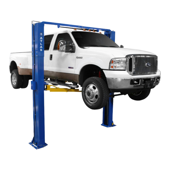
I. PRODUCT FEATURES AND SPECIFICATIONS CLEAR-FLOOR DIRECT-DRIVE MODEL FEATURES Model PV10PX (See Fig. 1) · Direct-drive design, minimizes the lift wear parts and breakdown ratio · Dual hydraulic cylinders, designed and made to high standards, utilizing imported oil seal in cylinder ·... - Page 4 Attention! Please make sure to place the arms in correct position before driving vehicle onto lift! Fig. 3...
-
Page 5: Installation Requirement
II. INSTALLATION REQUIREMENT A. TOOLS REQUIRED ✓ Rotary Hammer Drill (Φ19) Carpenter’s Chalk ✓ ✓ Hammer Screw Sets ✓ ✓ Level Bar Tape Measure (7.5m) ✓ ✓ English Spanner (12") Pliers ✓ ✓ Ratchet Spanner With Socket (28 Socket Head Wrench (3 ✓... - Page 6 B. Equipment storage and installation requirements. The equipment should be stored or installed in a shady, normal temperature, ventilated and dry place. C. The equipment should be unloaded and transferred by forklift. Fig.5 D. SPECIFICATIONS OF CONCRETE (See Fig. 6) Concrete must adhere to the specifications listed below, failure to do so may result in lift and/or vehicle falling.
- Page 7 III. INSTALLATION STEPS A. Location of installation Check and ensure the installation location (concrete, layout, space size etc.) is suitable for lift installation. B. Use a carpenter’s chalk line to establish installation layout of columns (See Fig. Chalk Line 139 ½” Fig.
- Page 8 3. Take out the outer column in the middle, lift the upper column with a forklift or hoist, loosen the bolts of the upper package stand, take out the parts in the inner column (See Fig. 10). Fig. 10 4. Lift the lower column with a forklift or hoist, take down the package stand, then take off the lower outer column, take out the parts in the inner column (See Fig.
- Page 9 Pars box (115) Shipment parts list Fig.13 Fig.12 6. Check the parts of the parts bag 1 according to parts bag list (See Fig. 14). Fig. 14 Check the parts of the parts bag 2 according to parts bag list (See Fig.
- Page 10 D. Install parts of extension columns (See Fig. 16). Fig.16...
- Page 11 E. Install hydraulic cylinder Apply thread tape to both ends of extended straight fitting, connect the 90° fitting, connect both to cylinder, and then install the cylinder in the carriages (See Fig. 17) Offside column Powerside column Insert the installed cylinder into Column Place fitting in the cylinder toward the hole in the column...
- Page 12 F. Install columns Lay down two columns on the installation site parallel, position the power side column according to the actual installation site. Usually, it is suggested to install power side column on the front-right side from which vehicles are driven to the lift. This lift is designed with 2-section columns.
- Page 13 G. Position the columns Position the columns on the installation layout of base plate. Install the anchor bolts. Check the columns plumbness with level bar and adjust with shims if the columns are not vertical. Do not tighten the anchor bolts (See Fig.20) Width between columns:112 1/8”...
- Page 14 H. Install overhead top beam 1. With help of the hook of top beam, put one side of top beam on top of the extension column and connect the top beam to extension column with bolts, tighten the bolts. (See Fig. 21) Hook on the extension columns Tighten the bolts...
- Page 15 2. Assemble overhead top beam, tighten the columns anchor bolts (See Fig. 22) Tighten the anchor bolts with ratchet spanner with socket Torque of tighten the anchor bolts is 150 NM or 110 Ft Lbs. Fig.22...
- Page 16 Installing the limit switch control bar and limit switch (See Fig. 23) Limit switch control bar Loosen screw of drive rod for adjustment, tighten the screw after adjustment Connect the blue wire to terminal 11# on limit switch and terminal A1 on AC Limit switch connected contactor of power unit with cable...
- Page 17 J. Install safety device (See Fig. 24 & Fig. 25) Fig. 24 Power side safety device Fig. 25 Offside safety device...
- Page 18 K. Raise the carriages up by hand so they are locked at the same level (See Fig. 26). Fig. 26...
- Page 19 L. Install cables 1. High setting cable connection: 1.1 Take out the carriage’s plastic cover, pass cable through from the bottom of the carriages and pull out from the opening of the carriages, then screw on the two cable nuts (See Fig.
- Page 20 1.2 Connecting cable for high setting (See Fig. 28) High setting Cable 2 Cable 1 Cable 1 Fig. 28...
- Page 21 2. Low setting cable connection (See Fig. 29) Note : Cable should go inside of the carriage. Low Setting Cable 2 Cable 1 Cable 2 Fig. 29...
- Page 22 Install power unit (See Fig. 30) Fig.30...
- Page 23 N. Install oil hose High setting and low setting oil hose routing & assembly (See Fig. 31) (48, 49 Only for high setting) Oil Hose connecting at high setting Oil hose pass through the cable clamp on top beam Oil hose and wire pass through the support bracket Oil hose connected...
- Page 24 O. Install safety cable. Install safety cable from offside safety device to power-side safety device, pass through the top beam (See Fig. 32) Safety cable Safety cable pass through small pulley bracket Install safety cable from offside safety device Safety cable connected with the power-side safety device Fig.32...
- Page 25 P. Install wire protective cover (See Fig. 33). Install with M6*35 Cup head screw 1, Tighten the cup head screw M6*40 2, Install wire protective cover and tighten the screw Install wire protective cover for holding hose protecting plastic hose. Fig.33...
- Page 26 Q. Install lifting arms and adjust the arm locks 1. Install lifting arms (See Fig. 34) 2. Lower the carriages down to the lowest position, then use the socket head wrench to loosen the socket bolt (See Fig.35) 3. Adjust moon gear as direction of arrow (See Fig.36) 4.
- Page 27 R. Install electrical system Connect a power source matching the requirement of the Power Unit. Note: 1. Install the limit switch 2. For the safety of operators, the ground wire must be used. Single phase motor (See Fig. 38). 1. Connecting the two power supply lines (active wire L and neutral wire N) to terminals L1, L2 of AC contactor respectively.
- Page 28 Motor Line Remove this line before connecting the limit switch Fig. 39 Fig. 40 Three phase motor 1. Circuit diagram (See Fig. 41) Fig. 41...
- Page 29 Connection Step (See Fig. 42) a. Power supply line (L1, L2, L3) connected with terminals L1, L2, L3 of AC contactor respectively. b. Wire 12#(brown wire)of limit switch connected with terminal 4# of control button; Wire 11#(blue wire) connected with terminal A1 of AC contactor, Earth wire( yellow and green wire) of limit switch connected with the terminal earth wire of the motor.
-
Page 30: Exploded View
IV. EXPLODED VIEW Model 211SAC Fig.43... - Page 31 Item Part# Description Quantity 11217458 Power-side column (inner) 81523003 Power unit 10209003 Hex bolt 10209033 Washer 10217002 Washer 11217405 Power-side Safety Lock Cover 10217005 Plastic ball 11217006 Safety Lock handle 10206023A Hex Nut 10420026 Washer 11217004 Main Cam Lock 11217436 Large Spacer 10217030 Safety Spring...
- Page 32 Item Part# Description Quantity 10217008 Safety Spring 11217031 Offside Cam Lock 10217033 Locking Nut 10217032 Cable Lock Hold 10620079 Fitting 1002165001 Oil hose 11217029 Small Pulley Bracket 10217066 Hex Bolt 11217459 Offside column (Inner) 11209051B 1.5” Stackable adapter 11209052B 2.5” Stackable adapter 11209053B 5”...
- Page 33 Item Part# Description Quantity 10209038 Hex Bolt 11217037 Bottom pin 11217036 Bottom pulley 10217315 Lifting Arm assy. –front left 10217114A Rubber pad assy. 11680030B Rubber Pad frame 10420138 Socket Bolt M6*16 10209134 Rubber Pad 10217316 Lifting Arm assy. -front right 10201002 Hex bolt 10209034...
- Page 34 4.1 Lifting arm assy. - Rear (10217333)exploded view: Fig.44 Part Description 10206048 Socket bolt 10209039 Washer 10209022 Washer 11206049 Moon gear 11217329 Outer arm-rear 10201149 Cup head bolt 11217330 Inner arm-rear...
- Page 35 Lifting arm assy.-Front left (10217318)exploded view: Fig.45 Part Description 10206048 Socket bolt 10209039 Lock washer 10209022 Washer 11206049 Moon gear 11217323 Right Outer arm-Front 11209244 Middle arm-Front 10201149 Cup Head Bolt 11217334 Inner Arm-Front...
- Page 36 exploded view: 4.3 Lifting arm assy. -Front right(10217319) Fig.46 Part Description 10206048 Socket bolt 10209039 Lock washer 10209022 Washer 11206049 Moon gear 11217322 Left Outer arm-Front 11209244 Middle arm-Front 10201149 Cup Head Bolt 11217334 Inner Arm-Front...
- Page 37 4.4 Cylinder (10217056) exploded view: Fig.47 Cylinder parts list Description Item Par # 66-1 10209069 O-Ring 66-2 10209070 Bleeding Plug 66-3 10209071 Support Ring 66-4 10209072 Y-Ring 66-5 10209073 O-Ring 66-6 11209074 Piston 66-7 10209075 O-Ring 66-8 11217076 Piston Rod 66-9 11209077 Fitting for Piston Rod...
- Page 38 4.5 POWER UNIT EXPLODED VIEW 220V/60Hz, Single Phase Fig. 48...
- Page 39 Parts lift for 220V/60Hz/1 Phase Item Part# Description 81400180 Rubber Pad 81400250 Starting capacitor 81400200 Running capacitor 10420148 Cup Head Bolt with washer 81400066 Cover of Motor Terminal Box 81400363 Motor Connecting Shaft 80101013 Manifold block 10209149 Washer 81400276 Iron plug 81400259 Red rubber plug 85090142...
- Page 40 4.6, Illustration of hydraulic valve for power unit Oil return port Relief valve Release valve Check valve Throttle Oil outlet valve Handle for relief valve Fig. 49...
-
Page 41: Test Run
V. TEST RUN 1. Adjustment of synchronous cables (See Fig. 50) Use wrench to hold the cable end, meanwhile using ratchet spanner tighten the cable nut until the two cables are in the same tension. If the two vehicle carriages are not Synchronized Cable nut when lifting and lowering, please screw and tighten the cable nut on the lower side carriage. - Page 42 5. Test with load After finishing the above adjustments, test run the lift with a load. Run the lift in low position for several times first, raising and lowering, make sure the lift can raise and lower synchronously and the safety device can lock and release synchronously. Then test run the lift to full rise.
-
Page 43: Operation Instruction
VI. OPERATION INSTRUCTIONS Please read the safety tips carefully before operating the lift To lift vehicle 1. Keep work site near the lift clean and clear at all times; 2. Position carriages and lift arms to the lowest position; 3. Move shortest lift arms toward rear of lift; 4. -
Page 44: Maintenance
VII. MAINTENANCE SCHEDULE Monthly: 1. Re-torque the anchor bolts to 150 Nm or 110 Ft Lbs.; 2. Check all connectors, bolts and pins to insure proper mounting; 3. Lubricate cable with lubricant; 4. Make a visual inspection of all hydraulic hoses/lines for possible wear or leakage; 5. -
Page 45: Trouble Shooting
VIII.TROUBLE SHOOTING TROUBLE CAUSE REMEDY 1. Start button does not work 1. Replace Start button 2. Wiring connections are not in good 2.Repair all wiring connections Motor does not condition 3. Motor burned out 3. Repair or replace motor 4. AC contactor in damage 4. -
Page 46: Warranty
X. WARRANTY: This item is warranted for five (5) years on structural components, two (2) years on hydraulic cylinders, and one (1) year on electric or air / hydraulic power units from invoice date. Wear items are covered by a 90 day warranty.
Need help?
Do you have a question about the Atlas PV-10PX and is the answer not in the manual?
Questions and answers