Table of Contents
Advertisement
Advertisement
Table of Contents

Related Manuals for Atlas Equipment OH-10X


Summary of Contents for Atlas Equipment OH-10X
-
Page 2: Table Of Contents
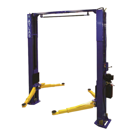
CONTENTS Product Features and Specifications ..........1 Installation Requirements.............3 Steps of Installation..………………………………………………………..…………..6 Exploded View ................18 Test Run ..................22 Operating Instructions ...............24 Maintenance ................24 Trouble Shooting ..............25 Parts List ………................26... - Page 3 DIRECT-DRIVED MODEL FEATURES MODEL OH10000X (See Fig.2) · Direct-drive design minimizes the lift wear on parts and breakdown ratio. · Dual hydraulic direct-drive cylinders are designed and made on ANSI standards, utilizing oil seal in cylinder. · Self-lubricating UHMW Polyethylene sliders and bronze bush. ·...
-
Page 4: Installation Requirements
II.INSTALLATION REQUIREMENT A. TOOLS REQUIRED Rotary Hammer Drill (19mm, ¾”) Carpenter’s Chalk Hammer Screw Driver Set 4 Foot Level Bar Tape Measure (7.5m, 25ft) Crescent Wrench (12") Pliers Ratchet Spanner With Socket (28mm Socket Head Wrench ... -
Page 5: Steps Of Installation
B. SPECIFICATIONS OF CONCRETE (See Fig. 2) Concrete specifications must be followed accordingly. Failure to do so may result in lift and/or vehicle falling. 1. Concrete must be thickness 4 inches minimum and without reinforcing steel bars, and must be completely cured before the installation. 2. -
Page 6: Packaged Lift And Hydraulic Power Unit (See Fig
Check the parts before assembly 1.Packaged lift and hydraulic power unit (see Fig. 4) Fig. 4 2. Move the lift aside with a fork lift or hoist, and open the outer packing carefully (See Fig. 5). ¾” Shipment Parts Serial No. Top Connecting Assy. - Page 7 6. Open the carton of parts and check the parts according to parts box list (See Fig. 15). Fig. 7 7.Check the parts of the parts bag according to parts bag list (See Fig. 8). Fig. 8...
- Page 8 D. Position the power side column Lay down two columns on the installation site parallel of each other. Position the power side column according to the actual installation site. Usually, it is suggested to install power side column on the front-right side from which vehicles are driven to the lift (See Fig.
- Page 9 F. Connecting cables cable passes through plate carriages cable passes through from the bottom of the carriages Fig. 11...
-
Page 10: Cx:3000Mm, 118
H. Position columns Position the columns upright on the installation layout. Drill holes for the power side column only. Install the anchor bolts. Do not tighten the anchor bolts. Position the offside column parallel to the power side column at the approximate width. Do not drill holes until overhead beam is installed (See Fig.12) Width between columns of... - Page 11 I. Assemble overhead top beams (See Fig.13). Fig. 13 J. Check the columns for plumb with a 4ft. level bar, and adjust with the shims. Tighten the anchor bolts (See Fig.14) Adjusting with the shims Tighten Fig. 14...
- Page 12 Install the limit switch control bar and limit switch (See Fig. 15). Socket Head Wrench loosen the Screw of drive Adjust Drive Rod adjustment of Limit Switch Limit switch connected with cable Fig. 15 NC: Normal contact...
- Page 13 L. Install the safety cable (See Fig. 16) Pass through safety cable View B View A Fig. 16...
-
Page 14: See Fig.
M. Install cables (See Fig. 17). Fig. 17... - Page 15 2. For model OH10000X (See Fig.18) Fig. 18...
- Page 16 O. Install power unit and oil hoses (See Fig. 19) After installing the fitting on the power unit, tighten the nut with 19mm Wrench Tighten all the hydraulic fittings, and fill the reservoir with hydraulic oil. Note: Use hydraulic fluid series 46. Fig.
- Page 17 P. Install lifting arms and adjust the arm locks 1. Install the lifting arms (See Fig. 20). 2. Lower the carriages down to the lowest position. Then use a wrench to loosen the 17mm nut on arm lock (See Fig. 21). Use the 17mm wrench to loosen the nut Fig.
- Page 18 Q. Install the electrical system Connect the power source on the data plate of power unit. Note: 1.The power source used must contain a ground wire. ATLAS single phase motor (See Fig. 24). 1. Connect the two power supply lines (fire wire L and zero wire N) to the terminals on the AC contactor marked L1, L2.
- Page 19 SPX single phase motor (See Fig. 27) 1. Power supply line (zero wire N) connected with wire 5# on the motor. 2. Wire 11# on the limit switch connected with wire 6# on the motor. 3. Wire 12# on limit switch connected with wire 4# on the control button. 4.
-
Page 20: Exploded View
Fig. 28 IV. EXPLODED VIEW Model OH10000X Model OH1000X Lifting arms... - Page 21 Fig. 29 Cylinders Fig. 30 SPX POWER UNIT, 220V/50Hz, Single phase Fig. 31...
- Page 22 ATLAS POWER UNIT 220V/50HZ/1 phase Fig. 32 Illustration of hydraulic valve for SPX & ATLAS power unit a. SPX manual power unit, 220V/50HZ, Single phase (See Fig. 44) Capacitor Relief valve Protective ring Oil return port Check valve Auxiliary hole Auxiliary hole Release valve Oil Outlet...
- Page 23 b. ATLAS manual power unit, 220V/50HZ, Single phase (See Fig. 34) Running capacitor Protective ring Start capacito Relief valve Oil return port Check valve Release valve Throttle valve Oil Outlet Handle for Release valve Fig. 34...
-
Page 24: Test Run
V. TEST RUN 1. Adjust the synchronizing cables (See Fig. 35) Use a wrench to hold the cable fitting, use a Ratchet to tighten the cable nut. Cable nut Make sure the two cables have the same tension so the two carriages lift at the same time. Press the plastic hole covers on the lifting carriages. - Page 25 5. Test with load Test run the lift with a load. Run the lift in low position several times, make sure the lift can raise and lower at the same time, and the safety device can lock and release at the same time.
-
Page 26: Maintenance
VI. OPERATION INSTRUCTIONS Please read the safety tips carefully before operating the lift To lift vehicle 1. Keep clean of site near the lift; 2. Position lift arms to the lowest position; 3. To shortest lift arms; 4. Open lift arms; 5. -
Page 27: Trouble Shooting
VIII.TROUBLE SHOOTING TROUBLE CAUSE REMEDY 1. Button does not work 1. Replace button 2. Wiring connections are not in good 2.Repair all wiring connections Motor does not condition 3. Motor burned out 3. Repair or replace motor 4. Height Limit Switch is damaged 4.Replace the Limit Switch 5. -
Page 28: Parts List
PARTS LIST FOR MODEL OH1000X Qty. Item Part# Description Note 211001 Power side Column 209002 Manual Power Unit 209003 Hex Bolt 209004 Rubber Ring 209005 Nylok Nut 209006 Safety Pin 209007 Safety Spring 209008 Safety Cover 209009 Cup Head Bolt 209010 Snap Ring 209114... - Page 29 Qty. Item Part# Description Note 209035 Moon Gear 209036 Lifting Arm- Front Left 213003 209037 Lifting Arm- Rear Left 213004 209038 Hex Bolt 209039 Lock Washer 680030 Rubber Pad Frame Support 206025A Foam Cushion 201005 Split pin 206025C Connecting Pin for Control Bar 202011 Control Bar 202011A...
- Page 30 Qty. Item Part# Description Note Parts List for Oil Hose, Fitting & Cable (See Fig.25-29) 209060 90° Fitting for power unit 211014 Oil hose 211016 T- fitting 211015A Oil hose 211020 Oil hose 211017 Extend 90° fitting for Cylinder 209066 Cable Nut 211018 Cable...
- Page 31 Parts for SPX manual power unit, 220V/50Hz/1 phase (See Fig.42) 201-1 209082 Motor 201-2 209109 Protective ring 201-3 209083 Motor connecting shaft 201-4 209084 Valve body 201-5 209085 Relief valve 201-6 209086 Lock washer 201-7 209087 Allen bolt 201-8 209088 Inlet pipe 201-9 209089...
- Page 32 Parts for PEAK manual power unit, 220V/50Hz/1 phase (See Fig.43) 201A-1 209082A Motor 201A-2 209109 Protective ring 201A-3 209112 AC contactor 201A-4 209083A Motor connecting shaft 201A-5 209084A Valve body 201A-6 209085A Relief valve 201A-7 209113 Throttle valve 201A-8 209086A Lock washer 201A-9 209087A...
- Page 33 Qty. Item Part# Description Note 201A-24 209105A Check valve 201A-25 209101A Release valve 201A-26 209102A Handle for release valve 201A-27 209103A Washer 201A-28 209104A 201A-29 209106A Gear pump 201A-30 209107A Oil return pipe 201A-31 209108A Filler cap Parts for PEAK manual power unit 380V/50Hz/3 phase (See Fig.43) 201B-1 209118A Motor...
Need help?
Do you have a question about the OH-10X and is the answer not in the manual?
Questions and answers