
Related Manuals for Atlas Equipment PV-15PX


Summary of Contents for Atlas Equipment PV-15PX
- Page 1 Read this entire manual before operation begins. Record below the following information which is located on the serial number data plate. Serial No. Model No. Date of Installation...
-
Page 2: Table Of Contents
Trouble Shooting ... 41 PV-15PX Parts List ..42 Warranty ....48... -
Page 3: Specifi Cations
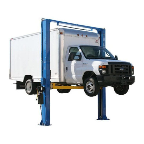
Specifi cations Clear-Floor Direct-Drive Model Features Model PV-15PX (See Fig. 1) • Direct drive hydraulic cylinder design, minimizes the lift wear parts and breakdown ratio • Dual hydraulic cylinders, designed and made on ANSI standards, utilizing NOK oil seal in cylinder •... - Page 4 Model PV-15PX Specifi cations Width Minimum Lifting Lifting Overall Style Lifting Height Overall Height Between Motor Capacity Time Width Columns Height Clear-fl oor 6.8 T 1872-2101mm 3812/4192/4497mm 3829mm 3137mm 145mm 4.0HP Direct-drive 15,000lbs 73 3/4”–82 3 /4” 150”/165”/177” 150 3/4”...
-
Page 5: Installation Requirement
Hammer Screw Drivers Level Tape Measure (25ft) Crescent Wrench (12”) Pliers Ratchet & Socket (28mm) Allen Head Wrench (3mm, 5mm, 8mm) Wrench set (mm) Vise Grips (10#, 13#, 14#, 15#, 17#, 19#, 24#, 27#, 30#) Fig. 3 Installation Requirement PV-15PX... - Page 6 2. Concrete must be in good condition and must have a test strength of 3,000psi minimum. 3. Floors must be level with no cracks or holes. Fig.4 Power Supply 220 volt single phase 30 amp breaker with minimum of 10 gauge wire Installation Requirement PV-15PX...
-
Page 7: Installation Steps
B. Use A Carpenter’s Chalk Line To Establish Installation Layout Of The Base Plate (See Fig. 5) Fig. 5 C. Check The Parts Before Assembly 1. Packaged lift, hydraulic power unit, and parts box (See Fig. 6). Fig. 6 Installation Steps PV-15PX... - Page 8 Fig. 8 4. Lift the upper column with a fork lift or hoist. Remove the bolts on the upper package stand. Remove the upper column and remove the parts in the lower column (See Fig. 9). Fig. 9 Installation Steps PV-15PX...
- Page 9 Remove the parts in the lower column (See Fig. 10). Open the package Fig. 10 6. Set aside the parts and check the parts according to the shipment parts list (See Fig. 11). Fig. 11 Installation Steps PV-15PX...
- Page 10 8. Check the parts in the part bag #1 according to parts bag list (See Fig. 13). Fig. 13 9. Check the parts in the parts bag #2 according to parts bag list (See Fig. 14). Fig. 14 Installation Steps PV-15PX...
- Page 11 D. Install The Hose Brackets And The Safety Release Cable Brackets (See Fig. 15) Use M6 x 20 Hex Bolts with M6 Nylock Nut & M6 Washer Fig. 15 Installation Steps PV-15PX...
- Page 12 (See Fig. 16). Power side Off side column column Fig. 16 The direction Use Tefl on tape to seal of fi tting NPT pipe threads. Do not use Tefl on tape on JIC hydraulic hose ends. Installation Steps PV-15PX...
- Page 13 2 sectional columns. Adjust the height according to your ceiling height. 1. When the ceiling height is over 4500mm (177 1/8”), connect the outer columns with the lower holes (See Fig. 17). Fig. 17 - High setting Installation Steps PV-15PX...
- Page 14 2. When the ceiling height is between 4200mm (165 3/8”) to 4500mm (177 1/8”), connect the outer columns with the middle holes (See Fig.18). Fig. 18 - Low setting PV-15PX Installation Steps...
- Page 15 3. When the ceiling height is less than 4200mm (165 3/8”), connect the outer columns with the upper hole. For this height setting you will need to purchase the shorter cables (part#217063) (See Fig. 19). Fig. 19 - Special Low Setting Installation Steps PV-15PX...
- Page 16 3. Drill 3/4” holes. If the top of the anchor exceeds 2 inches above the floor grade, you DO NOT have enough embedment. Adjust with the shims Width between columns: 123 1/2” 37/101 Fig. 20 Overall width: 150 3/4” Drilling Cleaning Bolting Installation Steps PV-15PX...
- Page 17 (See Fig. 21). Hook on the extension columns Use M12 x 30 Hex Bolts with M12 Nylock Nuts and Washers Tighten the bolts Fig. 21 Installation Steps PV-15PX...
- Page 18 2. Assemble overhead top beam, tighten the anchor bolts between 60 and 86 foot pounds. (See Fig. 22). Use M12 x 30 Hex Bolts with M12 Nylock Nuts and Washers Tighten Fig. 22 PV-15PX Installation Steps...
- Page 19 I. Installing The Limit Switch Control Bar And Limit Switch (See Fig. 23) Loosen Screw on the Drive Rod for adjustment, Tighten the screw after adjustment Normal Adjust Drive Rod contact on Limit Switch Limit Switch connected with cable Fig. 23 Installation Steps PV-15PX...
- Page 20 Fig. 24 - Power side safety device Use M10 x 10 Allen Head Set Screw 145° Spring 120° Spring Use M10 x 20 Hex Head Bolts to secure Fig. 25 - Offside safety device the pulley bracket Installation Steps PV-15PX...
- Page 21 K. Lift The Carriages Up By Hand And Lock Them At The Same Level (See Fig. 26) Fig. 26 Installation Steps PV-15PX...
- Page 22 1.1 Remove the carriages’ plastic covers. The cable passes through from the bottom of the carriages and is pulled out from the opening on the carriages. Install the two cable nuts (See Fig. 27). Tighten Cable connecting direction Cable Fig. 27 connecting direction Installation Steps PV-15PX...
- Page 23 1.2 Connecting the cable for high setting (See Fig. 28) High setting Cable 2 Cable 1 Cable 2 Fig. 28 Installation Steps PV-15PX...
- Page 24 2. Low setting cable connection. For ceiling heights between 4200mm (165 3/8”) to 4500mm (177 1/8”) (See Fig. 29). Low Setting Cable 2 Cable 1 Cable 2 Fig. 29 Installation Steps PV-15PX...
- Page 25 3. Special low setting cable connection. Suitable for ceiling heights less than 4200mm (165 3/8”) (See Fig. 30). This setting needs the optional short cable. Special low setting Cable 2 Cable 1 Cable 2 Fig. 30 Installation Steps PV-15PX...
- Page 26 M. Install Power Unit (See Fig. 31) Use M8 x 25 Hex Bolts with M8 Nuts & Washers Fig. 31 Installation Steps PV-15PX...
- Page 27 Oil hose Oil hose and wire pass through the support Oil hose passes bracket through the wire tube on top beam Fig. 32 Oil hose connected with 90 degree fi tting Oil hose connected with 90° fi tting Installation Steps PV-15PX...
- Page 28 Install the safety cable from the off side safety assembly to the power side safety assembly (See Fig. 33). Safety cable passes Safety through the small cable pulley bracket Install safety cable from offside safety assembly fi rst Safety cable connected with the power side safety assembly Fig. 33 Installation Steps PV-15PX...
- Page 29 P. Install Retainers (See Fig. 34) Install oil hose retainers using M6 x 8 screws Install retainer to fi x the oil hose Car in direction Fig. 34 Installation Steps PV-15PX...
- Page 30 Allen Head Wrench to loose the Allen Bolt Fig. 35 Fig. 36 Lock the bolts after Adjust moon gear moon gear and arm and arm lock lock engage well Moon Gear Arm lock Fig. 37 Fig. 38 Installation Steps PV-15PX...
- Page 31 1. Power supply wire (Fire wire L) is connected with wire 4# of control button. 2. Wire 3# of control button is connected with wire 6# of the motor. 3. Wire 5# of the motor is connected with Power supply wire (Null wire N). Fig. 39 Installation Steps PV-15PX...
-
Page 32: Pv-15Px Exploded View
PV-15PX Exploded View Fig. 40 PV-15PX PV-15PX Exploded View... - Page 33 Cylinders Fig. 41 PV-15PX Exploded View PV-15PX...
- Page 34 ATLAS Manual power unit (Fig. 42) 220V/60HZ, Single Phase Fig. 42 PV-15PX Exploded View PV-15PX...
- Page 35 Illustration Of Hydraulic Valve Fig. 43 PV-15PX Exploded View PV-15PX...
-
Page 36: Test Run
Lift the carriages to about 12 inches and loosen the bleeding plugs. Lower the lift until hydraulic fl uid seeps from the tops of the cylinders, then tighten the plugs. (See Fig. 45). Fig. 45 PV-15PX Test Run... - Page 37 NOTE: If the lift vibrates on the way up with a load, lubricate all pulley shafts and wear blocks. If the lift vibrates on the way down, the cylinders need to be bled. Fig. 46 Hydraulic System Test Run PV-15PX...
-
Page 38: Operation Instructions
2. Press the button of UP to raise the vehicle slightly, and then release the safety device, lower vehicle by pushing lowering handle. 3. Open the arms and position them to the shortest length. 4. Drive away the vehicle. PV-15PX Operation Instructions... -
Page 39: Maintenance Schedule
2. Check and adjust as necessary, equalizer tension of the cables to ensure level lifting. 3. Check columns for plumb. 4. Check rubber pads and replace as necessary. 5. Check safety lock device and make sure the condition is suitable. Maintenance Schedule PV-15PX... -
Page 40: Trouble Shooting
1. Safety locks may be engaged 1. Release the safeties 2. Release valve damaged 2. Repair or replace Lift can not lower 3. Safety cable broken 3. Replace 4. Oil system is jammed 4. Clean the oil system PV-15PX Trouble Shooting... -
Page 41: Pv-15Px Parts List
PV-15PX Parts List Item Part# Description Qty. Note 217174A Power side column 209002A Manual power unit 209003 Socket Bolt 209033 Lock washer 209005 Self locking Nut 217003 Power side lock cover 217004 Main cam lock 217069 Hex Bolt 206006 Washer... - Page 42 Hex Bolt 217047B Arm pin 209039 Lock washer 209023 Washer 206049 Moon gear 217052D Lifting arm 217122 Outer lifting arm 217123A Inner lifting arm Socket bolt 206048 Snap ring 206032 Limit ring 217043 Roll pin 206036 PV-15PX Parts List PV-15PX...
- Page 43 Limit bar bracket 420026 Lock washer 206023A Hex Nut 217005 Plastic ball 217006 Lock handle 217007 Large spacer 217030 Main spring 217009 Main lock 217010 Hex Bolt 217011 Hex Nut 217012 Small spacer 217050 Main lock pin PV-15PX Parts List PV-15PX...
- Page 44 For optional short cable (See Fig. 30) 217112 Short cable Parts For Hydraulic Cylinder (See Fig. 41) 61-1 209069 O-Ring 61-2 209070 Bleeding Plug 61-3 201029 Support Ring 61-4 201030 Y-Ring 61-5 201031 O-Ring 61-6 217074A Piston PV-15PX Parts List PV-15PX...
- Page 45 81400164 Filter 201-11 81400165 Hex bolt 201-12 81400027 Reservoir 201-13 81400166 Cross Bolt 201-14 81400167 Cover of Capacitor 201-15 81400087 Capacitor 201-16 81400168 Rubber Gasket 201-17 81400169 Hex bolt 201-18 81400062 Cover of Motor Terminal Box PV-15PX Parts List PV-15PX...
- Page 46 Push Button 201-20 81400105 Release Valve 201-21 81400033 Handle For Release Valve 201-22 81400170 Washer 201-23 81400171 Hex Nut 201-24 81400043 Check Valve 201-25 81400133 Gear Pump 201-26 81400157 Oil Return Pipe 201-27 81400113 Filler Cap PV-15PX Parts List PV-15PX...
-
Page 47: Warranty
Prices do not include any local, state or federal taxes. RETURNS: Products may not be returned without prior written approval from the Manufacturer. DUE TO THE COMPETITIVENESS OF THE SELLING PRICE OF THESE LIFTS, THIS WARRANTY POLICY WILL BE STRICTLY ADMINISTERED AND ADHERED TO. Warranty PV-15PX...
Need help?
Do you have a question about the PV-15PX and is the answer not in the manual?
Questions and answers