Table of Contents
Advertisement
Quick Links
Advertisement
Table of Contents

Related Manuals for Atlas Equipment LR10


Summary of Contents for Atlas Equipment LR10
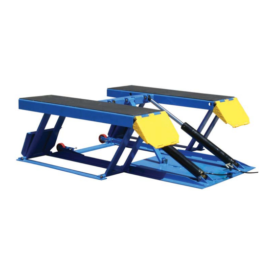
- Page 1 Replace This With Cover PDF...
- Page 2 Read this entire manual before operation begins. Record below the following information which is located on the serial number data plate. Serial No. Model No. Date of Installation...
-
Page 3: Table Of Contents
Contents Specifi cations ... . . 4 Installation Requirement ..5 Steps Of Installation ..6 Exploded View . -
Page 4: Specifi Cations
Raised Min. Lifting Overall Overall Runway Gross Model Motor capacity Height Height Time Length Width Width Weight 4.5T 600mm 105mm 1938mm 1780mm 456mm 450kg LR10 2.0/3.0HP 10000 lbs 23 5/8” 4 1/8” 76 1/4” 70” 18” 1000 lbs Specifications LR-10P... -
Page 5: Installation Requirement
Installation Requirement Tools Requirement Socket Head Wrench (8″) Screw Set Grease Gun Pliers Wrench sets (13#, 15#, 17#, 19#) Fig. 2 Power Requirement The electrical source must be 2.2KW minimum. The source cable size must be 2.5mm² and in good condition of contacting with fl oor. Installation Requirement LR-10P... -
Page 6: Steps Of Installation
Steps Of Installation A. Check The Parts Before Assembly Packaged lift, Parts box, Power Unit and Power Unit Stand. Move the parts aside, open the outer packing and check the parts according to the shipment parts list. Fig. 3 Open the parts box, check the parts according to the part list. Fig. - Page 7 Check the parts of the parts bag according to the parts bag list. Fig. 5 B. Install Hydraulic Power Unit Fig. 6 Steps Of Installation LR-10P...
- Page 8 C. Install Fitting And Connect Oil Hose Fig. 7 Steps Of Installation LR-10P...
- Page 9 D. Install Electrical System Connect the power source on the data plate of power unit. Note: For the safety of operators, the power wiring must contact the fl oor well. Pay attention to the direction of rotations when using three phrases motors. Atlas Single Phase Motor Connecting the two power supply lines (fi...
-
Page 10: Exploded View
Exploded View Fig. 9 Exploded View LR-10P... - Page 11 Cylinder Fig. 10 Roller Assembly Fig. 11 Exploded View LR-10P...
- Page 12 ATLAS 220V/60Hz/1 Single Phase Power Unit Fig. 12 Exploded View LR-10P...
- Page 13 Illustration Of Hydraulic Valve For Power Unit Atlas manual power unit 220V/60Hz/1Phase Running Protecting Capacitor Ring Start Capacitor Release Relief Valve Return valve Port Release Throttle Oil Outlet valve valve handle Check Valve Fig. 13 Exploded View LR-10P...
-
Page 14: Operation Instructions
Operation Instructions Install the oil hose between oil cylinder and power unit, connect well the power supply wire. The machine can be ready to use. The roller assembly must be disengage when lifting vehicle (See Fig. 16). To raise and lock the lift: Press the button up till the lift is raised to the required height and the locks are in engaged (See Fig. - Page 15 There are four fi xed holes in the machine, can fi x the machine on ground by 3/4 X 4 3/4” anchor bolts (See Fig. 18). Fig. 18 Operation Instructions LR-10P...
-
Page 16: Maintenance Schedule
Maintenance Schedule Monthly: Lubricate all moving parts with lubricant. Check all connectors, bolts and pins to insure proper mounting. Make a visual inspection of all hydraulic hoses/lines for possible wear or leakage. Every six months: Make a visual inspection of all moving parts for possible wear, interference or damage. -
Page 17: Trouble Shooting
Trouble Shooting TROUBLE CAUSE REMEDY 1. Button does not work 1. Replace button 2. Wiring connections are not in good 2. Repair all wiring Motor does condition connections not run 3. Motor burned out 3. Repair or replace motor 4. AC contactor burned out 4. -
Page 18: Parts List
Parts List (See Fig. 12, Fig.6-7) Parts List LR-10P... - Page 19 Item Part# Description 630001A Platform 206019 Snap ring 630003 Pin for Drive-thru Ramp 630106 Bracket Pin 630107 Bracket 630108 Drive-thru Ramp 630109 Connecting pin for cylinder 630006 Cylinder 630007 Cylinder base connecting pin 206032 Snap ring 630008 Frame support connecting pin (Upper) 630009 Frame support (Front) 630010...
- Page 20 630014 Safety bar set 630105 Pin for safety support 630111 Base frame 640024 Roller assembly 630102 Rubber block 620034 Rubber Pad 610070 Rubber Pad 420020B Hex Bolt 630015 Spring 209022 Washer 209056 Nylok Nut 209002 Manual power unit 209003 Hex Bolt 209005 Nylok Nut 640021...
- Page 21 Parts For Cylinder (See Fig. 13) Item Part# Description 630029 Bore weldment 630026 Piston Rod 201034 Bleeding plug 630030 Head cap 209078 Dust ring 201035 O - Ring 620049 O - Ring 630028 Piston 620050 O-Ring 8-10 630027 O-Ring 8-11 620054 Y-Ring 8-12...
- Page 22 Parts For Roller Assembly (See Fig. 14) Item Part# Description 20-1 630031 Roller Bracket 20-2 630032 Snap Ring 20-3 630033 Connecting Shaft 20-4 630034 Roller Shaft 20-5 640023 Roller Parts List LR-10P...
- Page 23 Parts For Atlas Manual Power Unit, 220V/60Hz/1 Phase (See Fig. 15) Item Part# Description 28A-1 209127A Motor 28A-2 209109 Protective Ring 28A-3 209112 A.C. Contactor 28A-4 209083A Motor Connecting Shaft 28A-5 209084A Valve Body 28A-6 209085A Relief Valve 28A-7 209113 Throttle Valve 28A-8 209086A...
- Page 24 28A-12 209090A Filter 28A-13 209091A Socket Bolt 28A-14 209092A Reservoir 28A-15 209093A Cup Head Bolt with washer 28A-16 209094A Cover of Capacitor 28A-17 209095A Start Capacitor 28A-17A 209095B Run Capacitor 28A-18 209096A Rubber Gasket 28A-19 209097A Cup Head Bolt with washer 28A-20 209098A Cover of Motor Terminal Box...
-
Page 25: Warranty
Warranty This item is warranted for two (2) years on structural components and one (1) year on air or electric hydraulic power units, pneumatic power units, cylinders and major components from date of invoice. Wear items are covered by a 90 day warranty.
Need help?
Do you have a question about the LR10 and is the answer not in the manual?
Questions and answers