
Subscribe to Our Youtube Channel
Related Manuals for Matelec FPC-30030


Summary of Contents for Matelec FPC-30030
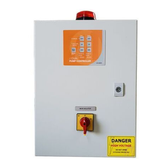
- Page 1 OW NE R’S OP ER ATION MANUAL Dua l Pu m p Co ntro ll e r Inst all ation an d O perating Instructio ns MOD EL: FP C-30030 PUMP ON PUMP ON FAULT FAULT MAIN ISOLATOR DOC: FPC-30030 VER 1.0...
- Page 2 Your Dual Pump Controller reflects the superior quality and attention to detail in design, engineering and manufacturing that has distinguished MATelec Products for decades. The controller incorporates the very latest in micro-processor technology, ensuring you, the owner/operator, of many years of functional, reliable and ‘user friendly’...
- Page 3 INSTALLATION WIRING CONNECTION DETAIL FPC-30030 MOUNTING 2 FLOAT SWITCH SYSTEM FRONT SIDE VIEW 1. Controller enclosure must be Input 2 Input 3 Input 4 A1 A2 mounted in a vertical position. Stop Start High Level Level Level Pump 1 Pump 2 2.
- Page 4 OPERA TIO N This controller can perform control functions for most Dual Pump pumping applications. It is more than likely that the control parameters have already been set up for your particular application, however, hereunder you will find details of the setup and configuration options. There are 6 DIP switches located on the lower side of the control module, which allows for selecting “mode”...
- Page 5 The basic logic on which a High or Low Level Alarm is determined, is set out in the Table below: Input 1 Input 2 Input 3 Input 4 Pump Alarm State Low Level Pump Stop Pump Start High Level Closed Open/Closed Open Open...
- Page 6 In pressure pump mode some of the optional features are disabled, including maximum run alternation, anti-seize and maximum idle timers In order to activate current loop mode the enclosure must be opened and jumper J10 moved to the “current loop enabled”...
- Page 7 CIRCUIT DIAGRAM PUMP ON PUMP ON FAULT FAULT 12Vdc TOL 1 TOL 2 CONTACTOR COILS A1 A2 KEYPAD CONNECTION KEYPAD CONNECTION PUMP 2 PUMP 2 PUMP 1 PUMP 1 PUMP 1 PUMP 2 PUMP 1 PUMP 2 PIN 1 PIN 1 FAULT FAULT FAULT...
- Page 8 Manual Pumping Mode FLASHING A prime loss fault has occurred. DISTRIBUTED BY: INSTALLATION DATE: SERIAL NUMBER: MANUFACTURED BY MATelec AUSTRALIA EMAIL: info@matelecaustralia.com.au MATelec reserves the right to alter technical specifications without notice.
Need help?
Do you have a question about the FPC-30030 and is the answer not in the manual?
Questions and answers