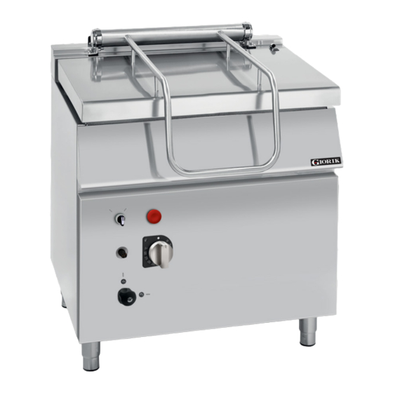
Giorik 700 Series Installation, Operation & Maintenance Manual
Bratt pan gas / electric
Hide thumbs
Also See for 700 Series:
- Installation and operation manual (52 pages) ,
- Installation, operation & maintenance manual (45 pages) ,
- Installation manual (29 pages)
Table of Contents
Advertisement
Quick Links
Advertisement
Table of Contents

Subscribe to Our Youtube Channel
Related Manuals for Giorik 700 Series


Summary of Contents for Giorik 700 Series
- Page 1 INSTALLATION / OPERATION / MAINTENANCE MANUAL (READ ALL INSTRUCTIONS BEFORE USE) 700/900 BRATT PAN (Gas / Electric) Models: 700 Series: 900 Series: BG7XMT BG94XAT / BG94XMT / BG96XAT BE7XMT BE94XAT / BE94XMT / BE96XAT Revision: A - 21/12/2021 - 1...
- Page 2 Page Intentionally Left Blank Due to continuous product research and development, the information contained herein is subject to change without notice. www.stoddart.com.au www.stoddart.co.nz Page 1...
- Page 3 4.0 Operation 1.1 Your New Giorik Product ....3 4.1 Gas Operation - Manual Tilt ....18 1.2 Australia and New Zealand Warranty .
- Page 4 Thank you for choosing this quality Giorik product. All Giorik products are designed and manufactured to meet the needs of food service professionals. By caring for and maintaining this new Giorik product in accordance with these instructions, will provide many years of reliable service.
-
Page 5: Warranty And Registration
700/900 1.0 Introduction Warranty & Registration 1.2 Australia and New Zealand Warranty 1.2.1 Warranty Period All Stoddart manufactured and distributed products are covered by Stoddart’s standard Australia and New Zealand Product Warranty (minimum 12 month on-site parts and labour, terms and conditions apply). Further to this standard warranty, certain products have access to an extended warranty. -
Page 6: General Precautions
1.0 Introduction 1.3 General Precautions When using any electrical unit, safety precautions must always be observed. • All units MUST be installed according to the procedures stated in the installation section of this manual • In the case of new personnel, training is to be provided before operating the equipment •... - Page 7 700/900 1.0 Introduction 1.4 Setting Up Information IMPORTANT To be installed only by an authorised service person WARNING Improper installation, adjustments, alterations, service or maintenance can cause property damage, injury or death 1.4.1 Handling • Use suitable means to move the unit; - For smaller items use two people - For large items a fork lift, pallet trolley or similar (the forks should reach completely beneath the pallet) 1.4.2 Unpacking...
-
Page 8: Specification
2.0 Specification 2.1 Specification 2.1.1 Giorik 700 Series 700 Series Model BG74XMT BE74XMT Gas Bratt Pan S/S Base Electric Bratt Pan S/S Base Description 50 Litre - Manual tilt 50 Litre - Manual tilt Weight 160kg 160kg Overall Height 965mm... - Page 9 10mm STODDART BG94XMT 72.0 MJ/H 15mm www.stoddart.com.au BG94XAT 72.0 MJ/H 15mm Description: Giorik; BG96XAT 86.4 MJ/H 10mm 900 Bratt Pan; Gas; 80 Ltr; Manual Tilt Pilot Burner - 700/900 Model No: Main burner gas injector Gas Approval No. (100th of a mm)
-
Page 10: Technical Drawing
2.0 Specification 2.2 Technical Drawing 2.2.1 BG74XMT 700 Series - Gas Model BG74XMT Overall Height 965mm Overall Depth 778mm Overall Width 800mm Weight 160kg Capacity Gas Connection 1/2 BSP, 43.2 MJ/H Natural / Universal LPG Natural Universal LPG Supply Gas Pressure 1.3 kPa... - Page 11 700/900 2.0 Specification 2.2.3 BG94XAT 900 Series - Gas Model BG94XAT Capacity 80 Litre Weight 170kg Overall Height 965mm Overall Depth 971mm Overall Width 800mm 1Ø + N + E Electrical Connection 240VAC / 50Hz / 0.1kW 10A plug & lead Gas Connection 1/2 BSP / 72 MJ/H Natural / Universal LPG...
- Page 12 2.0 Specification 2.2.5 BG96XAT 1200 900 Series - Gas Model BG96XAT Capacity 120 Litre Weight 200kg Overall Height 965mm Overall Depth 971mm Overall Width 1200mm 1Ø + N + E Electrical Connection 240VAC / 50Hz / 0.1kW 10A plug & lead 1092 Gas Connection 1/2 BSP / 86.4 MJ/H...
- Page 13 700/900 2.0 Specification 2.2.7 BE94XMT 900 Series - Electrical Model BE94XMT Capacity 80 Litre Weight 170kg Overall Height 965mm Overall Depth 978mm Overall Width 800mm 3Ø + N + E Electrical Connection 415VAC / 50Hz / 16.2kW Legend Electrical Connection Water Connection 1/2”...
-
Page 14: Installation
3.0 Installation 3.1 Positioning WARNING Improper installation, adjustments, alterations, service or maintenance can cause property damage, injury or death. 3.1.1 General Information • The unit must be installed under an extraction canopy • Have a smooth, level floor which can bear the weight of the unit at full load •... -
Page 15: Gas Connection
700/900 3.0 Installation 3.2 Gas Connection WARNING This unit must be installed by an authorised person/installer in accordance with this instruction manual, AS/NZS 5601 – Gas installations (installation and pipe sizing), local gas fitting regulations, local electrical regulations, local water regulations, local health regulations, Building Code of Australia and any other government authority. -
Page 16: Gas Conversion
3.0 Installation 3.3 Gas Conversion IMPORTANT Gas Conversion must only be carried out by an authorised person. Incorrect installation may void warranty If the unit is to be connected to a different type of gas than that for which it has been prepared, the nozzles must be replaced. Please contact Stoddart for the approved Gas conversion Kit and settings. -
Page 17: Final Check
700/900 3.0 Installation 3.3.3 Pilot Nozzle Replacement To replace the pilot nozzle: Close gas isolation valve and ensure the area is ventilated Remove the lower front panel Unscrew the nut “G”. Remove the nozzle (Fig.7) and replace it with the one for the type of gas chosen Re-install the nut “G”... -
Page 18: Electrical Connection
3.0 Installation 3.4 Electrical Connection 3.4.1 Information WARNING This unit must be installed in accordance with AS/NZS 60335.1 Some procedures in this manual require the power to the equipment to be turned off and isolated. Turn the power OFF at the power point and unplug the power supply lead by the plug body. -
Page 19: Operation
700/900 4.0 Operation 4.1 Gas Operation - Manual Tilt WARNING Hot surfaces! DO NOT TOUCH Contact with skin may cause burns WARNING DO NOT spray aerosols in the vicinity of the appliance when operating. 4.1.1 Controller Configuration Control Panel Symbol Description Pilot Flame °C... - Page 20 4.0 Operation 4.2 Gas Operation - Automatic Tilt WARNING Hot surfaces! DO NOT TOUCH Contact with skin may cause burns WARNING DO NOT spray aerosols in the vicinity of the appliance when operating. 4.2.1 Controller Configuration Control Panel Symbol Description Pilot Flame °C Temperature Range 50°C - 300°C...
- Page 21 700/900 4.0 Operation 4.3 Electric Operation - Manual Tilt WARNING Hot surfaces! DO NOT TOUCH Contact with skin may cause burns 4.3.1 Controller Configuration Control Panel Symbol Description Power On °C Temperature Range 50°C - 300°C Green Indicator Light Red Indicator Light Water Fill Tap Fig.11.
- Page 22 4.0 Operation 4.4 Electric Operation - Automatic Tilt WARNING Hot surfaces! DO NOT TOUCH Contact with skin may cause burns 4.4.1 Controller Configuration Control Panel Symbol Description Power On °C Temperature Range 50°C - 300°C Green Indicator Light Emergency Stop Tilt Dial Water Fill Tap Fig.12.
-
Page 23: Cleaning And Maintenance
700/900 5.0 Cleaning and Maintenance 5.1 Cleaning 5.1.1 Cleaning Schedule • Daily cleaning is required for the appliance, to help maintain and prolong the appliance efficiency • The appliance should be cleaned at the end of each service period • DO NOT USE: Wire brushes, steel wool/sponges, scrapers or other abrasive materials •... - Page 24 5.0 Cleaning and Maintenance 5.1.6 Cleaning Procedure (Daily) Isolate the unit from the power supply The appliance exterior should never be cleaned with direct water or high pressure jets Clean the inside of the unit using warm soapy water and a clean cloth, until all has been removed Empty the bratt pan and rinse For heavy soiling soak the base of the pan with warm soapy water for 10 minutes.
-
Page 25: Periodic Maintenance
700/900 5.0 Cleaning and Maintenance 5.2 Maintenance WARNING Maintenance tasks are only to be completed by authorised service people 5.2.1 Hi Temp Thermostat - Electric / Gas Automatic In order to avoid damage to the bratt pan (electric and gas automatic models) and to keep the operator and work environment safe, the Hi Temp thermostat automatically switches off the power to the unit. -
Page 26: Troubleshooting
5.0 Cleaning and Maintenance 5.2.3 Troubleshooting • If any faults/issues occur with the unit, follow the below troubleshooting procedures • If the troubleshooting procedures do not correct the problem, contact the Stoddart Service Department Problem Possible Causes Possible Corrective Action GAS MODELS Check the Gas Valve is fully open. - Page 27 700/900 Due to continuous product research and development, the information contained herein is subject to change without notice. www.stoddart.com.au www.stoddart.co.nz Page 26...
- Page 28 Australia Service / Spare Parts Sales Tel: 1300 307 289 Tel: 1300 79 1954 Email: service@stoddart.com.au Email: sales@stoddart.com.au Email: spares@stoddart.com.au Service Request www.stoddart.com.au Australian Business Number: 16009690251 New Zealand Service / Spare Parts Sales Tel: 0800 935 714 Tel: 0800 79 1954 Email: service@stoddart.co.nz Email: sales@stoddart.co.nz Email: spares@stoddart.co.nz...
Need help?
Do you have a question about the 700 Series and is the answer not in the manual?
Questions and answers