Table of Contents
Advertisement
Quick Links
Advertisement
Table of Contents

Related Manuals for Fluidwell F1-A-PD-OS Series


Summary of Contents for Fluidwell F1-A-PD-OS Series
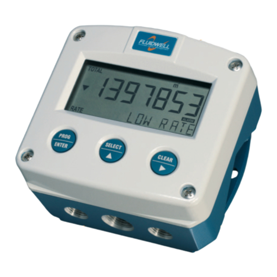
- Page 1 INDICATORS WITH ANALOG SENSOR INPUT WITH HIGH / LOW ALARMS ADDENDUM / INSTALLATION GUIDE FOR MODELS F113-A, F170-A AND F173-A FOR TYPE PD-OS: - 4 MECHANICAL RELAY OUTPUTS F-Series - Field mounted indicators for safe and hazardous areas. More info: www.fluidwell.com/fseries.
-
Page 2: Safety Instructions
Page 2 SAFETY INSTRUCTIONS ▪ Any responsibility is lapsed if the instructions and procedures as described in this manual are not followed. ▪ LIFE SUPPORT APPLICATIONS: The F1xx-A is not designed for use in life support appliances, devices, or systems where malfunction of the product can reasonably be expected to result in a personal injury. -
Page 3: About The Manual
WARRANTY AND TECHNICAL SUPPORT For warranty and technical support for your Fluidwell products, visit our internet site www.fluidwell.com or contact us at support@fluidwell.com. Hardware version : 03.01.xx Software version : 03.04.xx (F113-A) and 03.05.xx (F17x-A) -
Page 4: Table Of Contents
Page 4 CONTENTS MANUAL Safety instructions ..........................2 Disposal of electronic waste ....................... 2 Safety rules and precautionary measures ..................2 About the manual ..........................3 Warranty and technical support ......................3 Contents manual ..........................3 Installation ..........................5 4.1. General directions ..................... -
Page 5: Installation
Page 5 INSTALLATION 4.1. General directions • Mounting, electrical installation, start-up and maintenance of this device may only be carried out by trained persons authorized by the operator of the facility. Persons must read and understand this manual before carrying out its instructions. •... -
Page 6: Dimensions- Enclosure
Page 6 4.3. DIMENSIONS- ENCLOSURE Aluminum and stainless enclosures (where “H” turns to “HS” for stainless, e.g. HA → HSA): 75 mm (2.95") 112 mm (4.40") 130 mm (5.12") 12mm 12mm 30mm 30mm 24mm 24mm M20 x 1,5 6 x M12 36mm 36mm 25mm... - Page 7 Page 7 75 mm (2.95") 112 mm (4.40") 130 mm (5.12") HK back box: (flat bottom) 75 mm (2.95") 118 mm (4.65”) 25mm 25mm D=20mm D=20mm 12mm 12mm 30mm 30mm 24mm 24mm D=12mm D=16mm D=16mm D=20mm 36mm 36mm 0.12” 0.12” D=22mm (0.866") 3x D=22mm (0.866”) 29.1 mm (1.15”)
-
Page 8: Installing The Hardware
The wire screens shall be terminated at one side to prevent wire loops. Inside of the Fluidwell unit, the different common ground terminals are connected to each other. It is advised, as illustrated, to terminate the wire screens in the vicinity of the sensor and to insulated the wire screen with a shrink tube at the Fluidwell unit side. -
Page 9: Protective Earth (Pe) Connections
Page 9 4.4.2. PROTECTIVE EARTH (PE) CONNECTIONS Inside the unit, different types of bonding and earthing are used. The common ground is mostly used for termination of the wire shields; the Protective Earth (PE) is used for electrical safety. For externally powered installations, route the Protective Earth (PE) grounding conductor into the enclosure together with the incoming power conductors. -
Page 10: Sensor Supply
Page 10 4.4.3. SENSOR SUPPLY Option PD: Sensor supply: 8.2V, 12V or 24 V: With this option, a real power supply for the sensor is available. The sensor can be powered with 8.2, 12 or 24 V DC (max. 50mA@24V). The voltage is selected by the two switches inside the enclosure. -
Page 11: Terminal Connectors
Page 11 4.4.4. TERMINAL CONNECTORS The following paragraphs describe the terminal connections and configurations that are specific for type PD-OS (4 mechanical relay outputs). For all other types of supply (PM, PF, PD, PX) in combination with types OA, OT and OR, please consult the standard user manual ‘FW_F1xx-A_vxxxx_xx_EN’. - Page 12 Page 12 Terminal 06-07; Unused Caution: Do not connect wires to these terminals; they are not in use for daily operation of the F1xx-A-OS. The onboard electronics hardwired to these terminals, should not be exposed to field wiring or “foreign voltages”. Terminal 08-09: Analog output (passive): A passive 4-20mA signal proportional to the flowrate for model F113-A or level, height or percentage for model F170A (see setup 72) and model F173-A (see setup 82) is available as standard.
- Page 13 Page 13 Terminal 10-11; relay output R1: This output is an alarm or pulse output according setup 81 (F113-A, F170-A) / setup 91 (F173-A). Terminal 12-13; relay output R2: This output is an alarm or pulse output according setup 82 (F113-A, F170-A) / setup 92 (F173-A). Terminal 14-15;...
- Page 14 Page 14 Terminal 26-31: type CB / CH / CI / CT - communication RS232 / RS485 / TTL (option) ▪ Full serial communications and computer control in accordance with RS232 (length of cable max. 15 meters) or RS485 (length of cable max. 1200 meters) is possible. ▪...
- Page 15 Page 15 FW_F1xxAOS_v1901_02_EN (addendum).docx...
- Page 16 Page 16 Fluidwell B.V. FW_F1xxAOS_v1901_02_EN (addendum).docx PO box 6 Voltaweg 23 Website: www.fluidwell.com 5460 AA Veghel 5466 AZ Veghel Find your nearest representative: www.fluidwell.com/representatives The Netherlands The Netherlands © 2019 Fluidwell B.V. - FW_F1xxAOS_v1901_02_EN (addendum).docx...
Need help?
Do you have a question about the F1-A-PD-OS Series and is the answer not in the manual?
Questions and answers