Table of Contents
Advertisement
Quick Links
Advertisement
Table of Contents

Related Manuals for Fluidwell F1-A-PD-OS Series


Summary of Contents for Fluidwell F1-A-PD-OS Series
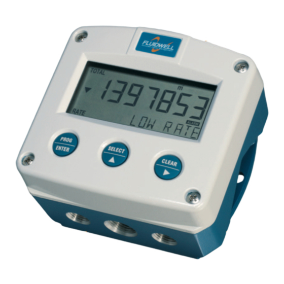
- Page 1 INDICATORS WITH ANALOG SENSOR INPUT WITH HIGH / LOW ALARMS ADDENDUM / INSTALLATION GUIDE FOR MODELS F113-A, F170-A AND F173-A FOR TYPE PD-OS: - 4 MECHANICAL RELAY OUTPUTS F-Series - Field mounted indicators for safe and hazardous areas. More info: www.fluidwell.com/fseries.
-
Page 2: Safety Instructions
▪ Intrinsic safe applications: follow the instructions as mentioned in Chapter 5 and consult “Fluidwell F1..-..-XI - Documentation for Intrinsic safety”. DISPOSAL OF ELECTRONIC WASTE • The WEEE Directive requires the recycling of disposed electrical and electronic equipment in the European Union. -
Page 3: About The Manual
WARRANTY AND TECHNICAL SUPPORT For warranty and technical support for your Fluidwell products, visit our internet site www.fluidwell.com or contact us at support@fluidwell.com. Hardware version : 03.01.xx Software version : 03.04.xx (F113-A) and 03.05.xx (F17x-A) -
Page 4: Table Of Contents
Page 4 CONTENTS MANUAL Safety instructions ..........................2 Disposal of electronic waste ....................... 2 Safety rules and precautionary measures ..................2 About the manual ..........................3 Warranty and technical support ......................3 Contents manual ..........................3 Installation ..........................5 4.1. General directions ..................... -
Page 5: Installation
Page 5 INSTALLATION 4.1. General directions • Mounting, electrical installation, start-up and maintenance of this device may only be carried out by trained persons authorized by the operator of the facility. Persons must read and understand this manual before carrying out its instructions. •... -
Page 6: Dimensions- Enclosure
Page 6 4.3. DIMENSIONS- ENCLOSURE 75 mm (2.95") 112 mm (4.40") 130 mm (5.12") 12mm 12mm 30mm 30mm 24mm 24mm M20 x 1,5 6 x M12 36mm 36mm 25mm 25mm 1/2"NPT 1/2"NPT 1/2"NPT 30mm 30mm 0.12" 0.12" M16 x 1,5 M16 x 1,5 3x 1/2"NPT M20 x 1,5... - Page 7 Page 7 75 mm (2.95") 112 mm (4.40") 130 mm (5.12") HK back box: (flat bottom) 75 mm (2.95") 118 mm (4.65”) 25mm 25mm D=20mm D=20mm 12mm 12mm 30mm 30mm 24mm 24mm D=12mm D=16mm D=16mm D=20mm 36mm 36mm 0.12” 0.12” D=22mm (0.866") 3x D=22mm (0.866”) 29.1 mm (1.15”)
-
Page 8: Installing The Hardware
The wire screens shall be terminated at one side to prevent wire loops. Inside of the Fluidwell unit, the different common ground terminals are connected to each other. It is advised, as illustrated, to terminate the wire screens in the vicinity of the sensor and to insulated the wire screen with a shrink tube at the Fluidwell unit side. -
Page 9: Aluminum Enclosure - Field Mounted
Do not use the terminal 00 to connect the protective earth wire, the 00 and the common ground terminals are internally connected. Be careful, to prevent damage to equipment when you connect different power supplies (sensor, PLC, etc.). Inside the Fluidwell display, the common grounds are internally connected to each other. -
Page 10: Plastic (Grp) Enclosure
Page 10 4.4.4. PLASTIC (GRP) ENCLOSURE The PE connection The F1xx-A in a GRP enclosure meets the requirements of class 2 (double insulated). Therefore the incoming PE wire is terminated with an insulating end cap. Type PM (110-230V AC) Type OR (8-24V AC) Type OR (8-30V DC) 4.4.5. -
Page 11: Terminal Connectors
Page 11 4.4.6. TERMINAL CONNECTORS The following paragraphs describe the terminal connections and configurations that are specific for type PD-OS (4 mechanical relay outputs). For all other types of supply (PM, PF, PD, PX) in combination with types OA, OT and OR, please consult the standard user manual ‘FW_F1xx-A_vxxxx_xx_EN’. - Page 12 Page 12 Terminal 08-09: Analog output (passive): A passive 4-20mA signal proportional to the flowrate for model F113-A or level, height or percentage for model F170A (see setup 72) and model F173-A (see setup 82) is available as standard. When a power supply is connected but the output is disabled, a 3.5mA signal will be generated.
- Page 13 Page 13 Mechanic relay output - R1, R2, R3, R4 INTERNAL EXTERNAL maximum DEVICE 240V AC - 0.5A maximum DEVICE 240V AC - 0.5A maximum DEVICE 240V AC - 0.5A maximum DEVICE 240V AC - 0.5A Terminal 26-31: type CB / CH / CI / CT - communication RS232 / RS485 / TTL (option) ▪...
- Page 14 Page 14 FW_F1xxAOS_v1702_03_EN (addendum).docx...
- Page 15 Page 15 FW_F1xxAOS_v1702_03_EN (addendum).docx...
- Page 16 Page 16 Fluidwell B.V. FW_F1xxAOS_v1702_03_EN (addendum).docx PO box 6 Voltaweg 23 Website: www.fluidwell.com 5460 AA Veghel 5466 AZ Veghel Find your nearest representative: www.fluidwell.com/representatives The Netherlands The Netherlands © 2019 Fluidwell B.V. - FW_F1xxAOS_v1702_03_EN (addendum).docx...
Need help?
Do you have a question about the F1-A-PD-OS Series and is the answer not in the manual?
Questions and answers