Table of Contents
Advertisement
Quick Links
Page 1
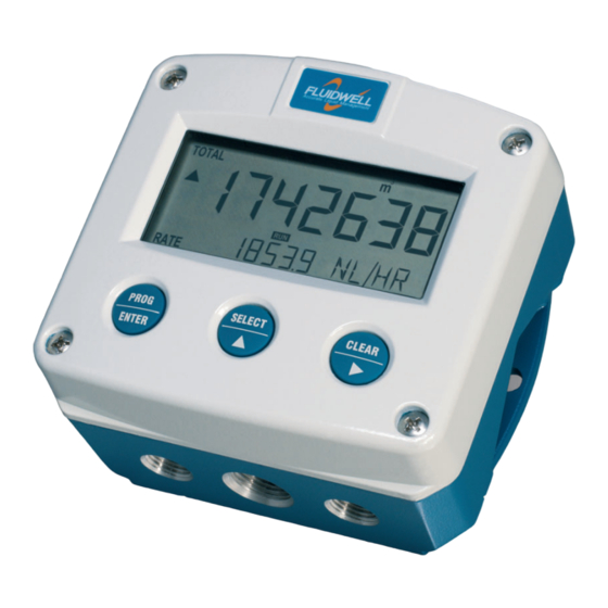
F-Series - Field mounted indicators for safe and hazardous areas.
F127-P-EL-TP
DIFFERENTIAL FLOW COMPUTER
temperature compensation for corrected liquid volume
Signal input flowmeter: pulse, Namur and coil
Signal input temperature: PT100
Output: (0)4-20mA / 0-10V ref. corrected flow rate, Scaled pulse ref.
accumulated total
Options: Intrinsically safe, Modbus communication and backlight
FW_F127PELTP_v1702_02_EN
More info: www.fluidwell.com/fseries.
Advertisement
Table of Contents

Related Manuals for Fluidwell F127-P-EL-TP


Summary of Contents for Fluidwell F127-P-EL-TP
- Page 1 Signal input flowmeter: pulse, Namur and coil Signal input temperature: PT100 Output: (0)4-20mA / 0-10V ref. corrected flow rate, Scaled pulse ref. accumulated total Options: Intrinsically safe, Modbus communication and backlight FW_F127PELTP_v1702_02_EN F-Series - Field mounted indicators for safe and hazardous areas. More info: www.fluidwell.com/fseries.
-
Page 2: Safety Instructions
Intrinsically safe applications: follow the instructions as mentioned in Chapter 0 and consult “Fluidwell F1..-..-XI - Documentation for Intrinsic safety” DISPOSAL OF ELECTRONIC WASTE The WEEE Directive requires the recycling of disposed electrical and electronic equipment in the European Union. -
Page 3: About The Manual
A "note !" indicates actions or procedures which, if not performed correctly, may indirectly affect operation or may lead to an instrument response which is not planned. WARRANTY AND TECHNICAL SUPPORT For warranty and technical support for your Fluidwell products, visit our internet site or contact us at www.fluidwell.com... -
Page 4: Table Of Contents
Page 4 CONTENTS MANUAL SAFETY INSTRUCTIONS........................2 DISPOSAL OF ELECTRONIC WASTE ....................2 SAFETY RULES AND PRECAUTIONARY MEASURES ..............2 ABOUT THE MANUAL ........................3 WARRANTY AND TECHNICAL SUPPORT ..................3 CONTENTS MANUAL ......................... 4 INTRODUCTION ........................5 System description ........................5 OPERATIONAL ........................ -
Page 5: Introduction
Page 5 1 INTRODUCTION SYSTEM DESCRIPTION Functions and features The flow computer, model F127-P is a microprocessor driven instrument for the calculation of differential flow measurement applications using flow equations for liquids. This product has been designed with a focus on: ... -
Page 6: Operational
Page 6 Configuration The F127-P is designed for use in many types of applications. For that reason, a setup menu is available to program the F127-P according to your specific requirements. The setup includes several important features, such as K-Factors, engineering units, signal selection, power management (to extend battery life-time), etc. -
Page 7: Operator Information And Functions
Page 7 OPERATOR INFORMATION AND FUNCTIONS In general, the F127-P operates in the operator mode. The shown information depends on the settings which are made in the setup menu. The signal from the connected sensor is processed by the F127-P in the background, independent from R U N the selected display refresh rate. -
Page 8: Configuration
Page 8 3 CONFIGURATION This and the following chapters are exclusively meant for electricians and non-operators. In these, an extensive description of all software settings and hardware connections are provided. Mounting, electrical installation, start-up and maintenance of this device may only be carried out by trained persons authorized by the operator of the facility. - Page 9 Page 9 The SELECT/▲ key and the CLEAR/► key are used for navigation. The explanation assumes that you are in the submenu TOTAL. When you are: in the first setting and you navigate to the previous setting, the F127-P goes back to the related main menu.
-
Page 10: Setup Menu - Settings
Page 10 3.1.1 SETUP MENU - SETTINGS TOTAL-A unit L; m3; kg; lb; GAL; USGAL; bbl; no unit decimals 0000000; 111111.1; 22222.22; 3333.333 K-factor 0.000010 - 9999999 decimals K-factor 0 - 6 FLOW RATE-A unit mL; L; m3; mg; g; kg; ton; gal; bbl; lb; cf; rev; - - - - (no unit); scf; nm3; nL; p time /sec;... -
Page 11: Explanation Of Setup-Menu 1 - Total-A
Page 11 PULSE mode signed; not negative; separated width 0.001 – 9 decimals 0000000; 111111.1; 22222.22; 3333.333 amount 0.001 – 9999999 COMMUNICATION speed 1200; 2400; 4800; 9600 address 1 - 247 mode bus-rtu; bus-asc; off OTHERS model F127-P software version nn:nn:nn serial no. -
Page 12: Explanation Of Setup-Menu 2 - Flow Rate-A
Page 12 3.1.3 EXPLANATION OF SETUP-MENU 2 - FLOW RATE-A The settings for total and flow rate are entirely separate. In this way, different engineering units can be used for each e.g. cubic meters for total and liters for flow rate. FLOW RATE-A 21 unit This setting is used to select the engineering unit for the indication of the flow... -
Page 13: Explanation Of Setup-Menu 3 - Total-B
Page 13 3.1.4 EXPLANATION OF SETUP-MENU 3 - TOTAL-B The engineering units are the same as used in SETUP-menu 1 - Total-A. TOTAL-B K-factor This setting is used to set the K-Factor for the total (B). With the K-Factor, the flowmeter pulse signals are converted to a quantity. -
Page 14: Explanation Of Setup-Menu 6 - Power Management
Page 14 stationary Shown flow rate: as soon as the flow rate is lower than SETUP 54 or negative, the stationary flow rate (SETUP 54) is shown. Shown total: as soon as the flow rate is lower as SETUP 54 or negative, stationary totalization (SETUP 55) will be activated. -
Page 15: Explanation Of Setup-Menu 7 - Flowmeter
Page 15 3.1.8 EXPLANATION OF SETUP-MENU 7 - FLOWMETER The F127-P is able to handle several types of input signal. The pickup / signal is selected with: SETUP 71 (Input A), Read also chapter 4 SETUP 72 (Input B), Read also chapter 4. The selections "active pulse"... -
Page 16: Explanation Of Setup-Menu 9 - Formula
Page 16 filter value Response time on step change of analog value. (Time in seconds). influence 1.8 sec 3.5 sec 5.6 sec 11 sec 3.5 sec 7.0 sec 11 sec 23 sec 5.3 sec 10 sec 17 sec 34 sec 8.8 sec 17 sec 29 sec... -
Page 17: Explanation Of Setup-Menu B - Pulse
Page 17 Example: Calculate the cut-off. Rate-min: 0L/min [4mA], Rate-max: 100 L/min [16mA], Cut-off: 2% Required rate [L/min]: (rate-max - rate-min)*cut-off: (100-0)*2%=2.0L/min Output [mA]: rate-min + (rate-max*cut-off): 4+(16*2%)=4.32mA tune-min The (0)4mA or 0V value can be tuned precisely with this setting. The initial minimum analog output value is (0)4mA or 0V. -
Page 18: Explanation Of Setup-Menu C - Communication (Option)
This product is designed for the connection to a communication network. Products with a communication option do not include cyber security functions. Fluidwell cannot take any responsibility for the cyber security, omissions or errors in the communication safety. To maintain a... -
Page 19: Installation
Page 19 4 INSTALLATION GENERAL DIRECTIONS Mounting, electrical installation, start-up and maintenance of this device may only be carried out by trained persons authorized by the operator of the facility. Persons must read and understand this manual before carrying out its instructions. ... -
Page 20: Dimensions- Enclosure
Page 20 DIMENSIONS- ENCLOSURE 75 mm (2.95") 112 mm (4.40") 130 mm (5.12") 12mm 12mm 30mm 30mm 24mm 24mm M20 x 1,5 6 x M12 36mm 36mm 25mm 25mm 1/2"NPT 1/2"NPT 1/2"NPT 30mm 30mm 0.12" 0.12" M16 x 1,5 M16 x 1,5 3x 1/2"NPT M20 x 1,5 15 15... - Page 21 Page 21 75 mm (2.95") 112 mm (4.40") 130 mm (5.12") HK back box: (flat bottom) 75 mm (2.95") 118 mm (4.65”) 25mm 25mm D=20mm D=20mm 12mm 12mm 30mm 30mm 24mm 24mm D=12mm D=16mm D=16mm D=20mm 36mm 36mm 0.12” 0.12” D=22mm (0.866") 3x D=22mm (0.866”) 29.1 mm (1.15”)
-
Page 22: Installing The Hardware
The wire screens shall be terminated at one side to prevent wire loops. Inside of the Fluidwell unit, the different common ground terminals are connected to each other. It is advised, as illustrated, to terminate the wire screens in the vicinity of the sensor and to insulated the wire screen with a shrink tube at the Fluidwell unit side. -
Page 23: Aluminum Enclosure - Field Mounted
Do not use the terminal 00 to connect the protective earth wire, the 00 and the common ground terminals are internally connected. Be careful, to prevent damage to equipment when you connect different power supplies (sensor, PLC, etc.). Inside the Fluidwell display, the common grounds are internally connected to each other. -
Page 24: Plastic (Grp) Enclosure
Page 24 4.4.4. PLASTIC (GRP) ENCLOSURE The PE connection The F127-P in a GRP enclosure meets the requirements of class 2 (double insulated). Therefore the incoming PE wire is terminated with an insulating end cap. Type PM (110-230V AC) Type OR (8-24V AC) Type OR (8-30V DC) FW_F127PELTP_v1702_02_EN... -
Page 25: Terminal Connectors
Page 25 4.4.5. TERMINAL CONNECTORS For Intrinsically safe applications: read chapter 5. Refer to Appendix A: Technical Specification Fig. 7: Overview of terminal connectors - Standard configuration and options SENSOR SUPPLY For type PB/PC; PX; AP: There is no real sensor supply out available. Only a limited power supply is available. - Page 26 Page 26 Set the sensor supply 1. Make the F127-P safe. If applicable, mind the battery power. 2. Open the F127-P and carefully remove the cable-connectors and the protective cover. 3. Find and set the switches and select the V as required.
- Page 27 Page 27 Terminal 05-06 (R1) / 03-04 (R2); scaled pulse output SETUP 8 (read chapter 3) determines the pulse output function. The maximum pulse frequency of this output is 60Hz. If a relay output option has been supplied, be sure that the output frequency does not exceed 5Hz or else the life-time of the relay will be reduced significantly.
- Page 28 Page 28 Type AA An active 4-20mA signal proportional to the flow rate is available with this option. When the output is disabled, a 3.5mA signal will be generated on these terminals. Max. driving capacity 1000 Ohm @ 24VDC. (Requires power supply type PD/PF/PM). Fig.
- Page 29 Page 29 Type AP A passive 4-20mA signal proportional to the flow rate is available with this option. When a power supply is connected but the output is disabled, a 3.5mA signal will be generated. Max. driving capacity 1000 Ohm. This output does loop power the unit as well. Fig.
- Page 30 Page 30 Pulse-signal NPN / NPN-LP: The F127-P is suitable for use with flowmeters which have a NPN output signal. For reliable pulse detection, the pulse amplitude has to go below 1.2V. Signal setting NPN-LP employs a low-pass signal noise filter, which limits the maximum input frequency (read chapter 3). Fig.
- Page 31 Page 31 Reed-switch: The F127-P is suitable for use with flowmeters which have a reed-switch. To avoid pulse bounce from the reed-switch, it is advised to select REED LP - low-pass filter (read chapter 3). Fig. 21: Terminal connections - Reed-switch signal input (typical) NAMUR-signal: The F127-P is suitable for flowmeters with an NAMUR signal.
-
Page 32: Intrinsically Safe Applications
Certificates, safety values, control drawing and declaration of compliance can be found in the document named: “Fluidwell F1..-..-XI - Documentation for Intrinsic safety” For installation under ATEX directive: this Intrinsically safe device must be installed in accordance with the latest ATEX directive and product certificate KEMA 03ATEX1074 X. - Page 33 Page 33 Serial number and year of production This information can be looked-up in the setup menu: Others. Fig. 23: Example serial number (typical) Label information pulse input type – F1xx-..-..-XI (inside and outside the enclosure) Fig. 24: Label information - Intrinsically safe application (typical) FW_F127PELTP_v1702_02_EN...
-
Page 34: Terminal Connectors Intrinsically Safe Applications
3 and 4 and/or terminals 5 and 6; the maximum values for any of those circuits are those as defined for group IIB/IIIC. Terminal connectors F127-P-EL-TP-XI: For intrinsically safe applications, consult the safety values in the certificate. - Page 35 Page 35 Type AF - Intrinsically safe floating 4-20mA analog output - Terminal 7-8 A floating 4-20mA signal proportional to the flow rate is available with this option. When the output is disabled, a 3.5mA signal will be generated. Max. driving capacity 1000 Ohm @ 30V DC. It is required to link the minus from the analog output - terminal 7 - with a ground terminal of the unit;...
-
Page 36: Configuration Examples Intrinsically Safe Applications
Page 36 CONFIGURATION EXAMPLES INTRINSICALLY SAFE APPLICATIONS Fig. 28: F127-P-(AP)-(CT)-EL-TP-(OT)-PC-XI - Battery powered - IIB/IIC - IIIC FW_F127PELTP_v1702_02_EN... - Page 37 Page 37 Fig. 29: F127-P-AP-CT-EL-OT-(PX)-TP-XI - Output loop powered - IIB/IIC - IIIC FW_F127PELTP_v1702_02_EN...
-
Page 38: Maintenance
Repairs are only allowed to be carried out by the manufacturer or his authorized agent. REPAIR POLICY If you have any problem with your Fluidwell product and you wish to repair it, please follow the procedure below: a. Obtain a Return Material Authorization (RMA) from your supplier or distributor Together with the RMA, you need to complete a repair form to submit detailed information about the problem. -
Page 39: Battery Replacement
Page 39 BATTERY REPLACEMENT 6.4.1 SAFETY INSTRUCTIONS Handle the battery with care. A mistreated battery can become unsafe. Unsafe batteries can cause (serious) injury to persons. Only use batteries which are certified for use in hazardous areas. The use of standard batteries in hazardous area's is not safe and prohibited. -
Page 40: Technical Specification
Page 40 TECHNICAL SPECIFICATION Display Type High intensity reflective numeric and alphanumeric LCD, UV-resistant. Dimensions 90 x 40mm (3.5”x 1.6”) Digits Seven 17mm (0.67") and eleven 8mm (0.31"). Various symbols and measuring units. Refresh rate User definable: 8 times/sec - 30 secs. Type ZB LCD with LED backlight. - Page 41 Page 41 Sensor excitation Type PB / PC / PX 3V DC for low power pulse signals and 1.2V DC for coil pick-up. Type PD 1.2; 3; 8.2; 12; 24V DC - max. 50mA@24V DC Type PD-XI Intrinsically safe: Pulse signals: 1.2; 3; 8.2 - max. 7mA@8.2V DC. Type PF / PM 1.2;...
- Page 42 Page 42 Outputs Analog output Function transmitting differential flow rate. Accuracy 10 bit. Error < 0.05% - update 10 times a second. Software function to calibrate the 4.00mA and 20.00mA levels precisely within set-up. Load max. 1 kΩ Type AA Active 4-20mA output (requires type OA + PD, PF or PM).
-
Page 43: Problem Solving
Page 43 PROBLEM SOLVING In this appendix, several problems are included that can occur when the F127-P-EL is going to be installed or while it is in operation. Flowmeter does not generate pulses: Check: Signal selection; Pulse amplitude; ... -
Page 44: Communication
Page 44 COMMUNICATION General The product is fitted with the Modbus communication protocol and can be equipped with various physical interfaces like RS485 and RS232 (please see device datasheet for available options). The tables below show the various variables that can be accessed through the communication. Currently, the function codes supported are: ... - Page 45 Page 45 REGISTER VARIABLE TYPE VALUE / REMARKS ADDRESS RUN TIME REGISTERS [d] 516 40517 error status (bitfield) uint16 [d] 1: Display error [d] 2: data-storage error [h] 0x204 [d] 4: initialization error [d] 8: Analog input error [d] 16: PT100 ADC error [d] 32: Correction calculation factor (A) error [d] 64: Correction calculation factor (B) error [d] 128: TPC A calculation error...
- Page 46 Page 46 REGISTER VARIABLE TYPE VALUE / REMARKS ADDRESS FLOW RATE B REGISTERS [d] 227 40228 K-factor uint32 1...9999999 [h] 0x0E3 Representation: 0.000010…9999999 depending on variable 230 decimals K-factor [d] 230 40231 decimals K-factor uint16 0…6 [h] 0x0E6 REGISTER VARIABLE TYPE VALUE / REMARKS ADDRESS...
- Page 47 Page 47 REGISTER VARIABLE TYPE VALUE / REMARKS ADDRESS ANALOG OUTPUT REGISTERS [d] 112 40113 analog output uint16 0: disable 1: enable [h] 0x070 [d] 113 40114 rate-min uint32 0…9999999 [h] 0x071 Representation: unit, time, decimals depending on variables 48, 49, 50 [d] 116 40117 rate-max...
-
Page 48: Declaration Of Conformity
Page 48 DECLARATION OF CONFORMITY FW_F127PELTP_v1702_02_EN... -
Page 49: Index Of This Manual
Page 49 INDEX OF THIS MANUAL accumulated total functional description actual settings 50, 51 hardware version analog intrinsic safety floating output. Intrinsic safety 32, 34, 35, 38 flowrate min. IP classification intrinsically safe output. maintenance tune / calibrate manual version Analog output namur signal backlight... - Page 50 Page 50 IST OF CONFIGURATION SETTINGS SETTING DEFAULT DATE: DATE: TOTAL-A Enter your settings here 11 unit 12 decimals 0000000 13 K-factor 0000001 14 decimals K-factor FLOW RATE- A 21 unit 22 time unit /min 23 decimals 0000000 24 K-factor 0000001 25 decimals K-factor filter...
- Page 51 Page 51 IST OF CONFIGURATION SETTINGS SETTING DEFAULT DATE: DATE: ANALOG OUTPUT Enter your settings here A1 output disabled A2 rate-min 0000000 A3 rate-max 9,999,999 A4 cut-off A5 tune-min 0160 A6 tune-max 6656 A7 filter PULSE B1 mode signed B2 width 0 (off) B3 decimals B4 amount...
- Page 52 Page 52 Fluidwell B.V. PO box 6 Voltaweg 23 Website: www.fluidwell.com 5460 AA Veghel 5466 AZ Veghel Find your nearest representative: www.fluidwell.com/representatives The Netherlands The Netherlands Copyright: 2017 - FW_F127PELTP_v1702_02_EN...
Need help?
Do you have a question about the F127-P-EL-TP and is the answer not in the manual?
Questions and answers