Table of Contents
Advertisement
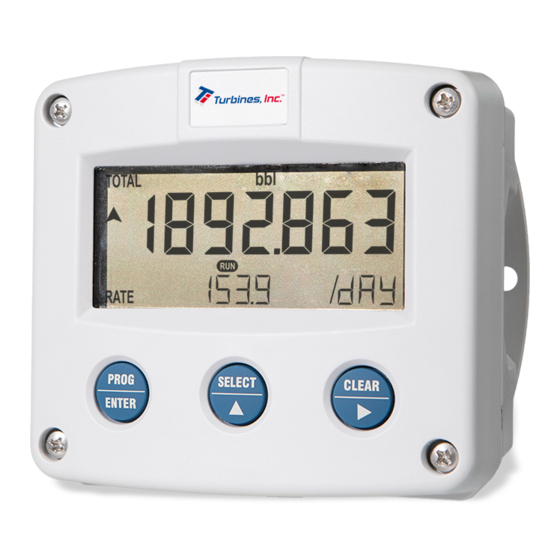
Page 1
F-Series - Field mounted indicators for safe and hazardous areas.
F103 WP
WEATHERPROOF FLOW TOTALIZER / FLOW LOGGER
with linearization, analog and pulse outputs
Signal input flowmeter: pulse, isolated active pulse and coil.
Signal outputs: analog 4-20mA reflecting flow rate, pulse
retransmission and scaled pulse reflecting total.
Hazardous area: Class I, Division 2, Groups A-D, T5
Options: Datalogging (Flow Logger), Modbus communication, external
reset and backlight.
FW-F103-P-XN-M_v2002_03_EN.docx
More info: www.fluidwell.com/fseries.
Advertisement
Table of Contents

Related Manuals for Fluidwell F103 WP


Summary of Contents for Fluidwell F103 WP
- Page 1 Page 1 F103 WP WEATHERPROOF FLOW TOTALIZER / FLOW LOGGER with linearization, analog and pulse outputs Signal input flowmeter: pulse, isolated active pulse and coil. Signal outputs: analog 4-20mA reflecting flow rate, pulse retransmission and scaled pulse reflecting total. Hazardous area: Class I, Division 2, Groups A-D, T5 Options: Datalogging (Flow Logger), Modbus communication, external reset and backlight.
-
Page 2: Safety Instructions
Page 2 SAFETY INSTRUCTIONS • Any responsibility is lapsed if the instructions and procedures as described in this manual are not followed. • LIFE SUPPORT APPLICATIONS: The F103-P is not designed for use in life support appliances, devices, or systems where malfunction of the product can reasonably be expected to result in a personal injury. -
Page 3: About The Operation Manual
MODEL REFERENCE The F103 WP is currently available in two main models: a Weatherproof Flow Totalizer and a Weatherproof Flow Logger. These main models are reflected in the configuration code of the F103 as shown in the table below. -
Page 4: Table Of Contents
Page 4 CONTENTS MANUAL SAFETY INSTRUCTIONS ............................ 2 DISPOSAL OF ELECTRONIC WASTE ........................ 2 SAFETY RULES AND PRECAUTIONARY MEASURES ..................2 ABOUT THE OPERATION MANUAL........................3 WARRANTY AND TECHNICAL SUPPORT ......................3 CONTENTS MANUAL ............................4 INTRODUCTION ............................. 5 System description of the F103-P .................... 5 OPERATIONAL ............................ -
Page 5: Introduction
Page 5 1 INTRODUCTION SYSTEM DESCRIPTION OF THE F103-P Functions and features The flow rate / totalizer, model F103-P is a microprocessor driven instrument designed to linearize the flowmeters flow curve and to show the flow rate, the total and the accumulated total. This product has been designed with a focus on: •... - Page 6 Page 6 Standard outputs • Configurable pulse output to transmit pulses representing a certain linearized total quantity. The pulse length can be set as desired with a maximum frequency of 500Hz. • Unscaled frequency output for retransmission of the incoming pulses as robust square wave forms.
-
Page 7: Operational
Page 7 2 OPERATIONAL GENERAL INFORMATION This chapter describes the daily use of the F103-P. This instruction is meant for users / operators. • The F103-P may only be operated by personnel who are authorized and trained by the operator of the facility. All instructions in this manual are to be observed. •... - Page 8 Page 8 arrows ▲▼ indicate the trend (increase or decrease) of the flowrate. By pressing the SELECT-key, the operator can scroll through the screens showing the various process values. After 30 seconds of inactivity, the display will automatically return to the main screen.
- Page 9 Page 9 Display historical day totals Besides directly reviewing the Current Day Total and Previous Day Total, a list of the last 15 Previous Day Totals can be reviewed. To enter the list, press the CLEAR-key for 3 seconds. Use the SELECT- and CLEAR-key to scroll up and down through the list of Previous Day Totals.
-
Page 10: Operator Alarms
Page 10 Fig. 7: Example of interval record 0003.B: Total (l) and event record 0128.A: Total Clear (r) To leave the record details and return to the record selection list, press the PROG-key again. To leave the DATALOG menu completely, press the PROG-key again for 3 seconds and the display will return to OPERATE level. -
Page 11: Quick Setup
Page 11 QUICK SETUP The Quick Setup allows users to quickly setup the most often used settings of the F103-P without having to go through the entire list of menu’s and settings of the Full Setup. Entering The Quick Setup can be reached from operator level by simply pressing the PROG-key. To use the Quick Setup, it must be enabled at SETUP-menu OTHERS: QUICK SETUP. - Page 12 Page 12 Quick Setup menu The following table shows the settings that are available in the Quick Setup menu. The numbers shown in the column SETUP indicate the corresponding setting in the Full Setup menu and are explained in detail in paragraph 3.3. Q-MENU CATEGORY SETTING...
-
Page 13: Configuration
Page 13 3 CONFIGURATION INTRODUCTION This and the following chapters are exclusively meant for electricians and non-operators. In these, an extensive description of all software settings and hardware connections is provided. • Mounting, electrical installation, start-up and maintenance of the instrument may only be carried out by trained personnel authorized by the operator of the facility. - Page 14 Page 14 Use the control panel to navigate through SETUP-level PROG-key When a function is selected, this key is used to start the programming sequence. When only a function group is selected (and no function), this key is used to scroll back a function group (e.g.
- Page 15 Page 15 Step 2b: Changing the selected item in a list SELECT-key This key is used to select the next item in the list (e.g. Disable → Enable). At the end of the list, the selection will wrap around to the first selection. CLEAR-key This key is used to select the previous item in the list (e.g.
-
Page 16: Configuration Settings
Page 16 CONFIGURATION SETTINGS All settings of the F103-P can be set via the control panel. As an alternative, you can also use the Remote Configuration Software which you can find on our website or through your supplier. Depending on the type of communication interface your device has, you might need a specific communication cable, which is available through your supplier. - Page 17 Page 17 ANALOG OUTPUT enable – disable RATE-MIN (4mA) 0000000 – 9999999 RATE-MAX (20mA) 0000000 – 9999999 CUT-OFF 0.0 – 9.9% TUNE-MIN (4mA) 0000 – 9999 TUNE-MAX (20mA) 0000 – 9999 FILTER 1 – 99 PULSE WIDTH 0.000 – 9.999 sec SOLID STATE OUTPUT enable –...
- Page 18 Page 18 EXPLANATION OF SETUP-MENU 1 – TOTAL 3.3.2 • First setup the flowmeter at SETUP MENU 5 - Flowmeter. It has a direct influence on the settings for Total. • Change of the type of flowmeter unit (SETUP 5.2 and SETUP 5.3) will cause the Total unit to jump to the default setting of the new flowmeter unit type.
- Page 19 Page 19 EXPLANATION OF SETUP-MENU 2 – FLOWRATE 3.3.3 • First setup the flowmeter at SETUP MENU 5 - Flowmeter. It has a direct influence on the settings for Flowrate. • Change of the type of flowmeter unit (SETUP 5.2 and SETUP 5.3) will cause the flowrate unit to jump to the default setting of the new flowmeter unit type.
- Page 20 Page 20 3.3.4 EXPLANATION OF SETUP-MENU 3 - DISPLAY DISPLAY FUNCTION This setting determines which information is shown on the main screen. The function can be set to indicate total, flowrate or accumulated total. • When “total” is selected, total is displayed with the large 12mm (0.47”) digits and flowrate is displayed with the 7 mm (0.28”) digits simultaneously.
- Page 21 Page 21 EXPLANATION OF SETUP-MENU 5 – FLOWMETER 3.3.6 To simplify the configuration of the Flowmeter, total and flow rate settings, the F103-P is equipped with an automatic unit conversion feature. This avoids different K-Factor calculations for Total and Flowrate and all configuration it done inside the Flowmeter menu. To use the automatic unit conversion, you only need to enter the (average) K-Factor and the related measurement unit.
- Page 22 Page 22 K-FACTOR UNIT This setting determines the measurement unit for the flowmeter. With automatic unit conversion, the units for Total and Flowrate are derived from this setting. The following can be selected: L – m3 – US gal – I gal – cf – Oil bbl AUTO-VOL: kg –...
- Page 23 Page 23 When the measured frequency is below the lowest or above the highest frequency given in the linearization points, the Meter Factor belonging to that frequency is used. Entering linearization points A table of 15 linearization points can be entered into the unit. It is advised to enter the linearization points in increasing order of frequency;...
- Page 24 Page 24 RATE-MIN (4mA) Enter the flowrate at which the output should generate the minimum signal (4mA) – in most applications at flowrate “0”. The number of decimals displayed depend upon SETUP 2.3. The measuring unit and time (L/min for example) depend on settings SETUP 2.1 and SETUP 2.2 and are displayed during editing.
- Page 25 Page 25 1.4 sec 2.8 sec 4.5 sec 9.0 sec 2.1 sec 4 sec 7 sec 14 sec 3.5 sec 7 sec 11 sec 23 sec 5.2 sec 10 sec 17 sec 34 sec 6.9 sec 14 sec 23 sec 45 sec EXPLANATION OF SETUP-MENU 8 –...
- Page 26 Page 26 3.3.10 EXPLANATION OF SETUP-MENU 9 – MODBUS COMMUNICATION (OPTION) The F103-P can optionally be equipped with a communication interface using the Modbus protocol (Type CX/CH). See Appendix C for a detailed explanation of the protocol, data types and available registers.
- Page 27 Page 27 When the F103-P is ordered with the datalogging option (type ZL), SETUP-menu 10 is extended to SETUP-menu 10 and SETUP-menu 11, as shown in the following paragraphs. 3.3.12 EXPLANATION OF SETUP-MENU 10 - DATALOGGING (WITH TYPE ZL) The function of the data log module is to record the performance of the F103-P and the amount of the medium that passed the sensor (e.g.
- Page 28 Page 28 DATALOG 10.1 LOG INT This setting selects the interval at which an interval records is created. The interval log logbook can hold up to 1000 records. When it is full, it will overwrite the oldest record first. The following interval times are available: Off - 5 min - 10 min - 15 min - 30 min - 1 hr - 2 hr - 4 hr - 6 hr - 8 hr 10.2 DAILY LOG...
-
Page 29: Installation
Page 29 4 INSTALLATION GENERAL DIRECTIONS • Mounting, electrical installation, start-up and maintenance of this instrument may only be carried out by trained personnel authorized by the operator of the facility. Personnel must read and understand this Operating Manual before carrying out its instructions. •... -
Page 30: Handling The F-Series Enclosure
Page 30 HANDLING THE F-SERIES ENCLOSURE REPLACING BATTERIES, DISCONNECTING LIVE CIRCUITS OR OPENING INSTALLED ENCLOSURES MAY ONLY BE DONE WHEN THE AREA IS FREE OF IGNITIBLE CONCENTRATIONS. 4.3.1 IDENTIFICATION To identify your F1-Series device, on the top-side of the unit, a label is applied. The labels shows the precise ordering code and specific certification data. -
Page 31: Mechanical Installation
Page 31 MECHANICAL INSTALLATION When installed according to Class I, Division 2, the F-Series enclosure is not suitable for panel mount installation. DIMENSIONS – ALUMINUM ENCLOSURE – TYPE HA, HL…HZ, HAA … HAZ 4.4.1 Fig. 15: Dimensions – Aluminum enclosures DIMENSIONS –... - Page 32 Page 32 4.4.5 USING CONDUITS AND CONDUIT HUBS WITH A PLASTIC ENCLOSURE It is possible to use the plastic enclosure in combination with 1 or 2 conduit hubs of 1/2". For this purpose, two ordering types have been added: 2x 1/2" conduit hub entries – fitted with internal earthing plate Type HGL: 1x 1/2”...
- Page 33 Page 33 4.4.6 MOUNTING The enclosure can be installed by itself or with the aid of a mounting plate in the configurations shown below. When the unit is installed on a wall or onto a meter, please use components and installation techniques that are suitable for the used materials.
-
Page 34: Electrical Installation
Page 34 ELECTRICAL INSTALLATION REPLACING BATTERIES, DISCONNECTING LIVE CIRCUITS OR OPENING INSTALLED ENCLOSURES MAY ONLY BE DONE WHEN THE AREA IS FREE OF IGNITIBLE CONCENTRATIONS. • Electro static discharge does inflict irreparable damage to electronics! Before installing or opening the F103-P, the installer has to discharge himself by touching a well-grounded object. - Page 35 Page 35 Metal enclosure When the F103-P is supplied with a metal enclosure (aluminum or stainless steel), the enclosure must be grounded in accordance with national and local electrical codes. To ground the F103-P, the PE conductor must be connected to the PE stud which is located in the metal back panel, as indicated in the image below.
- Page 36 Inside of the Fluidwell unit, the various common ground terminals are connected to each other. It is advised to terminate the wire screens in the vicinity of the sensor and to insulate the wire screen with a shrink tube at the F103-P side.
-
Page 37: Terminal Connectors
Page 37 TERMINAL CONNECTORS Take careful notice of all safety and precautionary measures indicated in paragraph 4.4: Electrical Installation and review paragraph 4.4.3 and 4.4.4 before applying any field or power supply wiring. To prevent the disconnection of live circuits in hazardous area, always use the supplied cable connectors with at least 5 poles to ensure proper strain relief. - Page 38 Page 38 Type OT / Type OG Two passive transistor outputs are available with this option with a maximum driving capacity of 300mA and 30V DC. The maximum pulse frequency of output D2 is 500Hz, for output D1 the minimum on and off-time is 50μs (max. 10kHz). 30V DC –...
- Page 39 Page 39 4.6.5 TERMINAL 09-11: FLOWMETER INPUT Three basic types of flowmeter signals can be connected to the unit: pulse, active pulse or sine- wave (coil). The screen of the signal wire must be connected to the common ground terminal 09 (unless earthed at the sensor itself).
- Page 40 Page 40 Pulse-signal PNP / PNP-LP The F103-P is suitable for use with flowmeters which have a PNP output signal. 3V is offered on terminal 11 which has to be switched by the sensor to terminal 10 (SIGNAL). For a reliable pulse detection, the pulse amplitude has to go above 1.2V.
- Page 41 Page 41 TERMINAL 12-13: EXTERNAL RESET – TYPE IB 4.6.6 With this function the total can be reset to zero with an external switch or passive signal. The Total resets only when the switch opens. When a Normally Closed (NC) contact is used, the local clear total function is disabled and a clear total is only possible with the external reset command.
- Page 42 Page 42 TERMINAL 17-18: ISOLATED PULSE INPUT – TYPE IG 4.6.8 The F103-P is suitable for use with an active flowmeter by connecting it to the isolated pulse input on terminals 17 and 18. The maximum frequency of the isolated pulse input is 3.5kHz and the active signal must switch between 0V and 3V ~ 30V to detect a pulse.
- Page 43 Page 43 4.6.10 TERMINAL C1-C6: COMMUNICATION INTERFACE The F103-P offers Modbus communication via a serial connection. Make sure that the hardware layer specific requirements are met to achieve reliable communication. Read the Modbus communication protocol and Appendix C. Besides the use of any Modbus compliant master, we offer special configuration software to completely configure the F103 and read-out logged data, available on our website.
-
Page 44: Maintenance
Page 44 5 MAINTENANCE GENERAL DIRECTIONS • Mounting, electrical installation, start-up and maintenance of this device may only be carried out by trained persons authorized by the operator of the facility. Persons must read and understand this manual before carrying out its instructions. •... -
Page 45: Battery Replacement
Page 45 BATTERY REPLACEMENT REPLACING BATTERIES, DISCONNECTING LIVE CIRCUITS OR OPENING INSTALLED ENCLOSURES MAY ONLY BE DONE WHEN THE AREA IS FREE OF IGNITIBLE CONCENTRATIONS. THE USE OF UNAPPROVED BATTERIES CAN INVALIDATE EXPLOSION SAFETY. Only use batteries that are approved by the manufacturer. Approved batteries can be ordered from your supplier. - Page 46 Page 46 5.3.2 REPLACE THE CLOCK BACKUP BATTERY To remove the clock backup battery, follow these instructions: 1. Open the enclosure and remove the main battery as indicated in the previous section. 2. Remove all connectors. 3. Remove the two screws that fasten the plastic cover and then carefully remove the plastic cover.
-
Page 47: Technical Specification
Page 47 TECHNICAL SPECIFICATION General Display Type High intensity reflective numeric and alphanumeric LCD, UV-resistant. Digits Seven 17mm (0.67") and eleven 8mm (0.31"). Various symbols and measuring units. Refresh rate User definable: 8 times/sec - 30 secs. Type ZB LCD with LED backlight. Improved readability in full sunlight and darkness. Enclosures General Die-cast aluminum, Stainless Steel or GRP (Glassfibre Reinforced Polyamide) enclosure with... - Page 48 Page 48 Inputs Flowmeter Type P non-isolated npn; npn-lp; reed; reed-lp; pnp; pnp-lp;coil-hi; coil-lo; isolated (Type IG) Active (3-30V dc) Frequency Minimum 0 Hz - maximum 7 kHz for total and flow rate. Maximum frequency depends on signal type and internal low-pass filter. E.g.
- Page 49 Page 49 Operational Operator functions Displayed information • Linearized flow rate, total and accumulated total • Current Day total, previous day total and 15 historical day totals • Indicating speedometer for flow rate • Total can be reset to zero by pressing the CLEAR-key twice •...
-
Page 50: Problem Solving
Page 50 PROBLEM SOLVING In this appendix, several problems are treated that can occur when the F103-P is going to be installed or while it is in operation. Flowmeter does not generate pulses: Check: • Signal selection; • Pulse amplitude; •... -
Page 51: Modbus Communication
Page 51 MODBUS COMMUNICATION General The product is fitted with the Modbus communication protocol and can be equipped with various physical interfaces like RS485 and RS232 (please see device datasheet for available options). The tables below show the various variables that can be accessed through the communication. Currently, the function codes supported are: •... - Page 52 Page 52 Runtime variables of the F103-P Reading flow rate, total, accumulated total or current day totals: When reading runtime variables, the given value may differ slightly from the value that is displayed on the display – this is due to the fact that the display is limited in the number of digits and may have a slower update rate.
- Page 53 Page 53 Historical previous day totals of the F103-P – Integer based – Contiguous read The read-out of historical previous day totals is done via 2 INDEXED variables containing the number of decimals and the value. These 2 variables can be read as one contiguous list of 3 registers (in a single read action). Reading is done by first selecting the right entry (day) through the index.
- Page 54 Page 54 [d] 2208 42209 Current day unit64 0.000…9999999999 [h] 0x8A0 total Representation: unit, decimals depending on variables 32, [d] 2216 42217 Previous uint64 0.000…9999999999 [h] 0x8A8 day total Representation: unit, decimals depending on variables 32, Flowrate VARIABLE TYPE VALUE / REMARKS HOLDING ADDRESS REGISTER...
- Page 55 Page 55 Linearization The linearization table is an INDEXED variable. Reading and writing the entries of the linearization table is done by first selecting the entry through the index. Valid values for the index are 0…14, which correspond with the linearization table entries 1 through 15. Indexes outside this range will result in an error being sent back.
- Page 56 Page 56 Modbus communication VARIABLE TYPE VALUE / REMARKS HOLDING ADDRESS REGISTER REGISTERS [d] 144 40145 speed uint16 0=1200 2=4800 4-9600HP 6=38400 [h] 0x090 (baudrate) 1=2400 3=9600 5=19200 7=57600 [d] 145 40146 modbus uint16 1…247 [h] 0x091 address [d] 146 40147 modbus uint16 0=off...
-
Page 57: Control Drawing F1Xx-Xn
Page 57 CONTROL DRAWING F1XX-XN FW-F103-P-XN-M_v2002_03_EN.docx... -
Page 58: Index Of This Manual
Page 58 INDEX OF THIS MANUAL actual settings Flowrate analog functional description cut-off value keys disable/enable main-function flowrate max. maintenance flowrate min. operational 7, 13, 29, 44 tune / calibrate Operator level clear total pass code clear total password power supply communication Pulse output Configuration... -
Page 59: List Of Figures In This Manaul
Page 59 LIST OF FIGURES IN THIS MANAUL Fig. 1: Typical application for the F103-P Fig. 2: Control panel Fig. 3: Example of display information during process Fig. 4: Example of historical day total from 8 days ago Fig. 5: Example of logbook selection screen Fig. - Page 60 Page 60 FW-F103-P-XN-M_v2002_03_EN.docx...
- Page 61 Page 61 FW-F103-P-XN-M_v2002_03_EN.docx...
- Page 62 Page 62 IST OF CONFIGURATION SETTINGS SETTING DEFAULT DATE: DATE: TOTAL Enter your settings here UNIT DECIMALS AUTO K-FACTOR FACTOR-X CLEAR PASSWORD CONTRACT HOUR 00:00 CURRENT DAY TOTAL ---- PREVIOUS DAY TOTAL ---- FLOWRATE UNIT TIME /min DECIMALS AUTO K-FACTOR CALCULATION PLS 10 30.0...
- Page 63 Page 63 LINEARIZE (continued) FREQUENCY 12 0.0Hz M-FACTOR 12 1.000000 FREQUENCY 13 0.0Hz M-FACTOR 13 1.000000 FREQUENCY 14 0.0Hz M-FACTOR 14 1.000000 FREQUENCY 15 0.0Hz M-FACTOR 15 1.000000 LINEARIZATION disable DECIMALS FREQUENCY ANALOG OUTPUT disable RATE-MIN (4mA) RATE-MAX (20mA) 99999 CUT-OFF 0.0% TUNE-MIN (4mA)
- Page 64 Page 64 Fluidwell B.V. PO box 6 Voltaweg 23 Website: www.fluidwell.com FW-F103-P-XN-M_v2002_03_EN.docx 5460 AA Veghel 5466 AZ Veghel Find your nearest representative: www.fluidwell.com/representatives The Netherlands The Netherlands Copyright: 2020 - FW-F103-P-XN-M_v2002_03_EN.docx...
Need help?
Do you have a question about the F103 WP and is the answer not in the manual?
Questions and answers