
Related Manuals for ARM DSTREAM


Summary of Contents for ARM DSTREAM
- Page 1 DSTREAM Setting up the Hardware Copyright © 2010 ARM. All rights reserved. ARM DUI 0481A (ID052210)
- Page 2 This document is intended only to assist the reader in the use of the product. ARM shall not be liable for any loss or damage arising from the use of any information in this document, or any error or omission in such information, or any incorrect use of the product.
- Page 3 CE Declaration of Conformity The system should be powered down when not in use. It is recommended that ESD precautions be taken when handling DSTREAM, RealView ICE, and RealView Trace equipment. The DSTREAM, RealView ICE, and RealView Trace modules generate, use, and can radiate radio frequency energy and may cause harmful interference to radio communications.
-
Page 4: Table Of Contents
2.10 Recovery mode ...................... 2-14 Chapter 3 System requirements for using DSTREAM Requirements for connecting the DSTREAM hardware .......... 3-2 Connecting the DSTREAM hardware ..............3-3 Hot-plugging and unplugging the debug cable ............3-5 Tracing with DSTREAM ................... 3-6 ARM DUI 0481A Copyright ©... - Page 5 List of Tables DSTREAM Setting up the Hardware Change history ..........................ii ARM DUI 0481A Copyright © 2010 ARM. All rights reserved. ID052210 Non-Confidential...
- Page 6 List of Figures DSTREAM Setting up the Hardware Figure 2-1 Rear of DSTREAM unit ....................... 2-6 Figure 2-2 Front of DSTREAM unit ......................2-6 Figure 2-3 Indicator LEDs ..........................2-7 Figure 2-4 DSTREAM probe ........................2-9 Figure 3-1 Connecting the DSTREAM hardware ..................3-3 ARM DUI 0481A Copyright ©...
-
Page 7: Conventions And Feedback
Highlights important notes, introduces special terminology, denotes internal cross-references, and citations. bold Highlights interface elements, such as menu names. Also used for emphasis in descriptive lists, where appropriate, and for ARM processor ® signal names. Feedback on this product... - Page 8 ARM also welcomes general suggestions for additions and improvements. ARM periodically provides updates and corrections to its documentation on the ARM Information Center, together with knowledge articles and Frequently Asked Questions (FAQs). Other information •...
- Page 9 Chapter 2 Introduction to DSTREAM The following topics introduce DSTREAM, and describe the software components: • About DSTREAM on page 2-2 • DSTREAM contents on page 2-3 • Availability and compatibility on page 2-4 • Introduction to the DSTREAM components on page 2-5 •...
-
Page 10: About Dstream
It enables you to connect a software ® debugger to an ARM processor-based target using a hardware interface such as JTAG or Serial Wire Debug (SWD). It also enables the collection of trace from the device for non-intrusive debug and code optimization. -
Page 11: Dstream Contents
Introduction to DSTREAM DSTREAM contents The DSTREAM product consists of: • A DSTREAM unit. • A DSTREAM probe. • Mains cables and a power supply that powers the DSTREAM unit. • An Ethernet cable. • A USB cable. • Probe cables: —... -
Page 12: Availability And Compatibility
The ability to access the target. • Tools to configure your debugger so that it can connect to the target through DSTREAM. Your debugger provides the user interface items, such as register windows and disassemblers, that make it possible to debug your application. -
Page 13: Introduction To The Dstream Components
Introduction to DSTREAM Introduction to the DSTREAM components The following topics introduce the components of the DSTREAM product, and describe how they fit together: • The DSTREAM unit on page 2-6 • The DSTREAM probe on page 2-9 • The DSTREAM firmware on page 2-11 •... -
Page 14: The Dstream Unit
Introduction to DSTREAM The DSTREAM unit The DSTREAM unit provides the hardware interface to enable a software debugger to control and trace multiple devices. The unit has ports at the rear for connecting to the host computer and to a power source. These ports are shown in the following figure. -
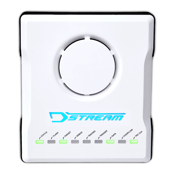
Page 15: Figure 2-3 Indicator Leds
PROBE Figure 2-3 Indicator LEDs When you power-up the DSTREAM unit, the DSTREAM logo on the top of the unit illuminates and the STATUS LED begins to flash. The STATUS LED remains illuminated to show that DSTREAM is in its ready state. - Page 16 2.5.1 See also Tasks • Recovery mode on page 2-14. Using the Debug Hardware Configuration Utilities: • Installing a firmware update or patch, ../com.arm.doc.dui0498a/Ciaihbfg.html. Concepts • The DSTREAM probe on page 2-9 • The DSTREAM firmware on page 2-11 •...
-
Page 17: The Dstream Probe
Cables for each of these connectors are supplied with DSTREAM. At any one time, use only the cables that are to be connected to the probe unit for the current debug trace session. The available... - Page 18 Introduction to DSTREAM • The debug host software on page 2-12 • Troubleshooting on page 2-13. Reference DSTREAM System and Interface Design Reference: • Supported target connectors on page 3-10. ARM DUI 0481A Copyright © 2010 ARM. All rights reserved. 2-10...
-
Page 19: The Dstream Firmware
Introduction to DSTREAM The DSTREAM firmware The DSTREAM firmware is located in the DSTREAM unit. It receives commands from the debugger and translates them into debug operations. The DSTREAM firmware contains specific sections of code for each ARM processor. These are called templates. -
Page 20: The Debug Host Software
Introduction to DSTREAM The debug host software The debug host software provides the interface between your debugger and the DSTREAM hardware that controls the target devices. It translates debugger commands, such as start, stop, and download, into control sequences for a particular processor. The debug software provides support for debugging on a wide range of ARM processors. -
Page 21: Troubleshooting
Introduction to DSTREAM Troubleshooting If you encounter problems when using your DSTREAM unit, see the following: • How do I confirm whether my DSTREAM unit is booting properly? 2.9.1 How do I confirm whether my DSTREAM unit is booting properly? The power-on sequence is: The DSTREAM backlight illuminates blue. -
Page 22: Recovery Mode
2.10 Recovery mode You can restore a DSTREAM unit that fails to boot by performing the following procedure: Press and hold the reset button on the DSTREAM unit for approximately 10 seconds. When the STATUS LED flashes red, release the button. RVI is now in recovery mode, and the STATUS LED flashes alternately red and green. - Page 23 System requirements for using DSTREAM The following topics describe the system requirements for DSTREAM, and how to connect the DSTREAM hardware to your host computer and target system. The topics also describe how to use some common parts of the debug software: •...
-
Page 24: Requirements For Connecting The Dstream Hardware
• one of the following cables, to connect the DSTREAM unit to the PC or the network: — the USB cable, to connect the DSTREAM unit directly to the PC using the USB port —... -
Page 25: Connecting The Dstream Hardware
DSTREAM product kit. 3.2.2 Procedure To connect the DSTREAM unit to your host computer and to the target hardware, carry out the following: Connect the host computer to the DSTREAM unit as shown in the following figure, using either the USB port or a TCP/IP network connection, as required: •... - Page 26 Use the RVConfig utility to configure your debug hardware unit. 3.2.3 See also Concepts • Requirements for connecting the DSTREAM hardware on page 3-2 • Hot-plugging and unplugging the debug cable on page 3-5 • Tracing with DSTREAM on page 3-6.
-
Page 27: Hot-Plugging And Unplugging The Debug Cable
You might want to connect the debug cable if you have a target that is operating without a DSTREAM unit connected and you want to examine the target to find out why it is behaving in a particular way. To do this, you must power-up the DSTREAM unit and configure the connection without affecting the state of the target. -
Page 28: Tracing With Dstream
DSTREAM to capture trace. DSTREAM is capable of capturing trace data into a cyclic buffer, and you can define the buffer size up to a maximum of 4GB. When a sufficient amount of trace data has been captured to fill the buffer, the FULL LED illuminates.
Need help?
Do you have a question about the DSTREAM and is the answer not in the manual?
Questions and answers