Table of Contents
Advertisement
Available languages
Available languages
Quick Links
Advertisement
Table of Contents

Related Manuals for Falcon F-700


Summary of Contents for Falcon F-700
- Page 1 20 September 2010 Rev: 01 All information, pictures, drawings and technical schematics are the property of Radio Zeeland DMP. Unauthorized copying is prohibited. The content of this manual is subject to change without prior notice.
- Page 2 Description 22-03-2010 Version 00 20-09-2010 Separate version F-700/F-701 Waarschuwing: In het product bevinden zich glazen onderdelen. Indien deze defect raken kunnen deze ernstige verwondingen veroorzaken. Bij defect dient u het apparaat spanningsloos te stellen en het ter reparatie aan te bieden bij uw dealer.
-
Page 3: Falcon F-700
Industrieweg 17, 4538 AG Terneuzen NL P.O. Box 1070, 4530 GB Terneuzen NL declare under our sole responsibility that the product, Falcon F-700 to which this declaration relates. Is in conformity with the following standard(s) or other normative document(s). EN 60945 (IEC 945 Third edition: 1996-11) Chapters 9, 10, 11 and 12. - Page 4 Version: Date: 21 September 2010 Document: Falcon700 Ver01 Page 4 of 34 First release: 04 February 2010...
-
Page 5: Table Of Contents
Falcon F-700 ..................... 8 2. Installatievoorschrift ......................9 2.1. algemeen........................9 2.2. Plaatsen van de intercom F-700 ................. 10 2.3. Aansluiten van de intercom ..................10 2.3.1. K1 : Voeding aansluitingen ................... 11 2.3.2. K3 : Microfoon en voetschakelaar ............... 11 2.3.3. - Page 6 2.1. General........................20 2.2. Placing the intercom F-700 ..................21 2.3. connecting the intercom ..................... 21 2.3.1. K1 : power supply ....................22 2.3.2. K3 : Microphone ....................22 2.3.3. K2 External connections ..................23 2.4. Set-up the F-700 ......................23 2.4.1 Set-up webpage ....................
-
Page 7: Nederlands
NEDERLANDS Version: Date: 21 September 2010 Document: Falcon700 Ver01 Page 7 of 34 First release: 04 February 2010... -
Page 8: Algemene Beschrijving / Technische Gegevens
In de verpakking treft u de volgende zaken aan: Manual Falcon F-700 Beschrijving meegeleverde items 1.2.1 Manual Hierin is het aansluiten, de functionaliteit en de bediening van de Falcon F-700 terug te vinden. 1.2.2 Falcon F-700 − Standaard uitgerust voor 99 posten met terugroepmogelijkheid −... -
Page 9: Installatievoorschrift
2. Installatievoorschrift 2.1. algemeen. Een Falcon intercom installatie bestaat minimaal uit de volgende delen: - Zichtinstrument / bediengedeelte Falcon F-700 - Blackbox Falcon F-701 - Multihub GEBRUIK GEEN ANDERE DAN DE VOORGESCHREVEN POSTEN. DIT ZOU PROBLEMEN KUNNEN GEVEN Version: Date:... -
Page 10: Plaatsen Van De Intercom F-700
2.2. Plaatsen van de intercom F-700 Installeer de F-700 op een makkelijk bereikbare plaats. Op de intercom kan de voetschakelaar RZ 707 en de zwanenhalsmicrofoon RZ 704 worden aangesloten. Ook deze moeten op een makkelijk bereikbare plaats worden geïnstalleerd, zo dicht mogelijk bij de F-700. -
Page 11: K1 : Voeding Aansluitingen
2.3.1. K1 : Voeding aansluitingen Op deze connector moet de voeding incl. afscherming worden aangesloten. De voeding moet liggen tussen de 18 en 36 V DC. De afscherming moet aan de behuizing worden aangesloten. 2.3.2. K3 : Microfoon en voetschakelaar Hier kan de microfoon (pin 1 en 2) en voetschakelaar (pin 3 en 4) worden aangesloten. -
Page 12: K2 Externe Aansluitingen
External speaker N 2.4. Instellen van de intercom Iedere F-700 heeft een eigen webbrowser waar de setup ingesteld/gewijzigd kan worden. Instellen van de intercom mag alleen gedaan worden door de installateur of service monteur. Bij onjuiste instellingen zal de intercom niet functioneren. - Page 13 Version: Date: 21 September 2010 Document: Falcon700 Ver01 Page 13 of 34 First release: 04 February 2010...
-
Page 14: Instellingen Webpagina
Ga dan via de webbrowser naar de webpagina van het apparaat. Stel hier het gewenste IP-adres in en of het gaat om een Falcon 700 of Falcon 701. Klik dan op OK. Als het apparaat opnieuw wordt opgestart zal deze het nieuwe IP-adres hebben. -
Page 15: Bedieningsvoorschriften
De intercom dient aangezet te worden door de ‘on/off/dim’ knop 3 seconden ingedrukt te houden. De achtergrond verlichting en de luister bar van de F-700 lichten op zodra de intercom is opgestart. Als er voor de eerste keer spanning op een F-700 wordt gezet zal deze, zodra deze is opgestart, automatisch aangaan. -
Page 16: Kanaalkeuze
3.1.6. Beantwoorden Als een oproepknop op een F-701 wordt ingedrukt wordt dit op de F-700 gemeld op het display en met een akoestisch signaal en het knipperen van het nummer van het sub station op het display. -
Page 17: Mob
Deze knop heeft dezelfde functionaliteit en bedieningsmogelijkheid als de knop op de F-700 bedieningsunit. Door de MOB knop 5 seconden in te drukken zal het alarm op alle posten afgaan. Het volume zal op alle stations naar de maximale stand gaan. -
Page 18: English
English Version: Date: 21 September 2010 Document: Falcon700 Ver01 Page 18 of 34 First release: 04 February 2010... -
Page 19: General Description/ Technical Data
1. General description/ Technical data Scope of delivery Falcon F-700 The packing of the equipment shall contain the following items: Manual Falcon F-700 Description of the items supplied with the equipment 1.2.1 Manual Here you will find information concerning the connections, functionality and operation of the F-700 1.2.2... -
Page 20: Installation Instruction
2. Installation instruction 2.1. General. A Falcon intercom installation contains at least the following units: - User interface/main station Falcon F-700 - Blackbox Falcon F-701 - Multihub DO NOT USE OTHER THAN PRESCRIBED STATIONS. THIS CAN CAUSE PROBLEMS! Version: Date:... -
Page 21: Placing The Intercom F-700
Place the F-700 at a place that is easily accessible. A footswitch RZ 707 and microfoon RZ 704 can be connected to the F-700. Those should also be installed at a place which is easily accessible and as close as possible to the F-700. 2.3. connecting the intercom The intercom should be connected with standard ethernet cable to a MultiHub. -
Page 22: K1 : Power Supply
2.3.1. K1 : power supply At this connection the power supply of the F-700 should be connected. The power supply should be between 18..36VDC. The screening should be connected to the housing. 2.3.2. K3 : Microphone The microphone should be connected to pin 1 and 2 and the footswitch to pin 3 and 4 of this connector. -
Page 23: K2 External Connections
The webpage of the F-700 is standard set to IP-address 192.168.2.100. Each device should have his own unique IP-address. With a webbrowser you can make a connection with the webpage of the F-700. The webpage address is known by the installer or service technician. The webpage looks like follows subject to change without prior notice. - Page 24 Version: Date: 21 September 2010 Document: Falcon700 Ver01 Page 24 of 34 First release: 04 February 2010...
-
Page 25: Set-Up Webpage
2.4.1 Set-up webpage In a new installation, each device (F-700 and F-701) should get his own, unique IP-address. Just connect one device in time and connect with the webpage of the device. Set the IP- address of the device en click on OK. After rebooting the device, it will have the new IP- address. -
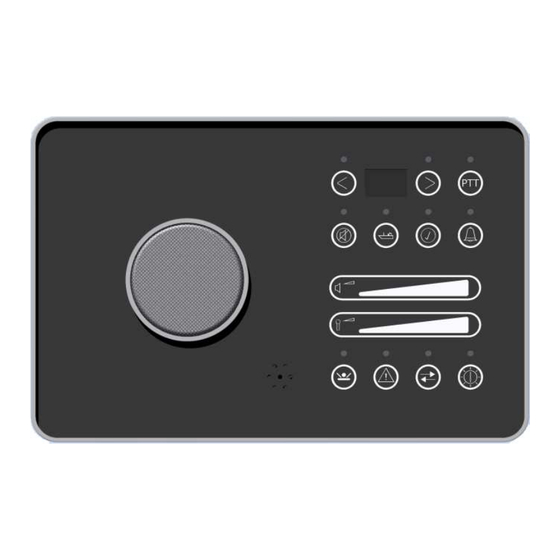
Page 26: Operation
Front F-700 3.1.1. Switch on The intercom F-700 can be switched on by pressing the ‘ON/OFF/Dim’ button for 3 seconds. The background illumination and listen volume will switch on if the system is started. After a reboot the system will start up automaticly. -
Page 27: Channels
F-700 will scroll through the list of channels. If the button is released, the selected channel number is flashing at the display and the F-700 will connect with the selected channel. If the connection is completed, the speak volume bar will switch on and the display shows the channel number. -
Page 28: Falcon F-701
3.2. Falcon F-701 The Falcon F-701 does not have a control unit but is only a blackbox. Externally there can be connected some in- and outputs. Refer to paragraph 2.3.3 and Appendix B for these connections. 3.2.1. External MOB switch This button has the same functionality as the MOB button on the F-700. -
Page 29: Appendix
Appendix Version: Date: 21 September 2010 Document: Falcon700 Ver01 Page 29 of 34 First release: 04 February 2010... -
Page 30: Appendix A Intercom Network Example
Appendix A Intercom Network example Version: Date: 21 September 2010 Document: Falcon700 Ver01 Page 30 of 34 First release: 04 February 2010... -
Page 31: Appendix B Connections F-700
Appendix B Connections F-700 Version: Date: 21 September 2010 Document: Falcon700 Ver01 Page 31 of 34 First release: 04 February 2010... -
Page 32: Appendix C Settings On Pcb
Appendix C Settings on PCB Version: Date: 21 September 2010 Document: Falcon700 Ver01 Page 32 of 34 First release: 04 February 2010... -
Page 33: Appendix D List Of Stations
Appendix D List of Stations Station nr. Location Sub / Main IP address 192.168.2…… □ □ 192.168.2…… □ □ 192.168.2…… □ □ 192.168.2…… □ □ 192.168.2…… □ □ 192.168.2…… □ □ 192.168.2…… □ □ 192.168.2…… □ □ 192.168.2…… □ □ 192.168.2……... - Page 34 Version: Date: 21 September 2010 Document: Falcon700 Ver01 Page 34 of 34 First release: 04 February 2010...
Need help?
Do you have a question about the F-700 and is the answer not in the manual?
Questions and answers