Table of Contents
Advertisement
Quick Links
Advertisement
Table of Contents

Related Manuals for R&S RTO2000


Summary of Contents for R&S RTO2000
- Page 1 ® R&S RTO2000 Oscilloscope Getting Started (=PïC2) 1332971902 Version 11...
- Page 2 Rohde & Schwarz GmbH & Co. KG. Trade names are trademarks of the owners. ® 1332.9719.02 | Version 11 | R&S RTO2000 ® Throughout this manual, products from Rohde & Schwarz are indicated without the symbol, e.g. ® R&S RTO2000 is indicated as R&S RTO.
-
Page 3: Table Of Contents
® Contents R&S RTO2000 Contents 1 Safety and regulatory information........5 1.1 Safety instructions................5 1.2 Labels on the product.................11 1.3 Warning messages in the documentation........12 1.4 Korea certification class A..............12 2 Key features................. 13 3 Documentation overview............ 14 3.1 Manuals and instrument help............14 3.2 Data sheet and brochure..............15... - Page 4 ® Contents R&S RTO2000 6 Operating the instrument............43 6.1 Means of manual interaction............. 43 6.2 Touchscreen display................44 6.3 App cockpit..................51 6.4 Working with waveforms..............52 6.5 Rohde & Schwarz smartgrid.............. 55 6.6 Toolbar....................56 6.7 Displaying results................65 6.8 Using dialog boxes................67 6.9 Entering data..................
-
Page 5: Safety And Regulatory Information
® Safety and regulatory information R&S RTO2000 Safety instructions Safety and regulatory information The product documentation helps you to use the product safely and efficiently. Follow the instructions provided here and in the Chapter 1.1, "Safety instructions", on page 5. - Page 6 ® Safety and regulatory information R&S RTO2000 Safety instructions Using the product requires specialists or specially trained personnel. These users also need sound knowledge of at least one of the languages in which the user interfaces and the product documentation are available.
- Page 7 ® Safety and regulatory information R&S RTO2000 Safety instructions Setting up the product Always place the product on a stable, flat and level surface with the bottom of the product facing down. If the product is designed for different positions, secure the product so that it cannot fall over.
- Page 8 ® Safety and regulatory information R&S RTO2000 Safety instructions ● Only use intact cables and route them carefully so that they cannot be dam- aged. Check the power cables regularly to ensure that they are undamaged. Also ensure that nobody can trip over loose cables.
- Page 9 ® Safety and regulatory information R&S RTO2000 Safety instructions tweezers or pliers to avoid injuries. When transporting the accessories, always use the box supplied with the probe. ● Prevent the probe from receiving mechanical shock. Avoid putting excessive strain on the probe cable or exposing it to sharp bends. Touching a broken cable during measurements can cause injuries.
- Page 10 ® Safety and regulatory information R&S RTO2000 Safety instructions ● The following effects can cause burns and fire or damage to the measurement site: – Eddy current loss can cause heating of the sensor head. – Dielectric heating can cause heating of cord insulation and other materials.
-
Page 11: Labels On The Product
® Safety and regulatory information R&S RTO2000 Labels on the product Cleaning the product Use a dry, lint-free cloth to clean the product. When cleaning, keep in mind that the casing is not waterproof. Do not use liquid cleaning agents. -
Page 12: Warning Messages In The Documentation
® Safety and regulatory information R&S RTO2000 Korea certification class A Warning messages in the documentation A warning message points out a risk or danger that you need to be aware of. The signal word indicates the severity of the safety hazard and how likely it will occur if you do not follow the safety precautions. -
Page 13: Key Features
® Key features R&S RTO2000 Key features The R&S RTO oscilloscopebrings various benefits in your daily work. Outstanding key features are: Best oscilloscope performance: ● Up to 16-bit vertical resolution ● Trigger on any detail you can see ● Quickly find signal faults with 1 Million waveforms/s ●... -
Page 14: Documentation Overview
® Documentation overview R&S RTO2000 Manuals and instrument help Documentation overview This section provides an overview of the R&S RTO user documentation. Manuals and instrument help You find the manuals on the product page at: www.rohde-schwarz.com/manual/rto Getting started manual Introduces the R&S RTO and describes how to set up and start working with the instrument, and describes basic operations. -
Page 15: Data Sheet And Brochure
® Documentation overview R&S RTO2000 Data sheet and brochure – eMMC Compliance Tests Procedures – PCIe Compliance Tests Procedures – DDR3 Compliance Tests Procedures – ScopeSuite Automation ● The following test fixture manuals are available: – R&S RT-ZF1 USB 2.0 Compliance Test Fixture Set –... -
Page 16: Release Notes, Open Source Acknowledgment
® Documentation overview R&S RTO2000 Application notes, application cards, videos www.rohde-schwarz.com/brochure-datasheet/rto Release notes, open source acknowledgment The release notes list new features, improvements and known issues of the cur- rent firmware version, and describe the firmware installation. The open source acknowledgment document provides verbatim license texts of the used open source software. -
Page 17: Preparing For Use
® Preparing for use R&S RTO2000 Choosing the operating site Preparing for use Here, you can find basic information about setting up the instrument for the first time or when changing the operating site. Lifting and carrying See: "Lifting and carrying the instrument"... -
Page 18: Setting Up The Product
® Preparing for use R&S RTO2000 Setting up the product Electromagnetic compatibility classes The electromagnetic compatibility (EMC) class indicates where you can operate the product. The EMC class of the product is given in the data sheet under "Gen- eral data". - Page 19 ® Preparing for use R&S RTO2000 Setting up the product 3. CAUTION! The product can fall over and cause injury. The top surface is too small for stacking. Never stack another product on top of the product. As an alternative, you can mount several products in a rack.
-
Page 20: Considerations For Test Setup
® Preparing for use R&S RTO2000 Considerations for test setup b) Mount the adapter kit. Follow the assembly instructions provided with the adapter kit. 2. Push the product onto the shelf until the rack brackets fit closely to the rack. -
Page 21: Connecting To Power
® Preparing for use R&S RTO2000 Connecting to power Preventing electrostatic discharge (ESD) Electrostatic discharge is most likely to occur when you connect or disconnect a DUT. ► NOTICE! Risk of electrostatic discharge. Electrostatic discharge can damage the electronic components of the product and the device under test (DUT). -
Page 22: Switching On Or Off
® Preparing for use R&S RTO2000 Switching on or off Switching on or off The instrument is switched on or off with the power switch and the [Power] key. The [Power] key is located in the bottom left corner of the front panel. The power switch is located at the rear panel of the instrument. -
Page 23: Connecting External Devices
® Preparing for use R&S RTO2000 Connecting external devices To disconnect from power The product is in the standby state. 1. NOTICE! Risk of data loss. If you disconnect the product from power when it is in the ready state, you can lose settings and data. Shut it down first. - Page 24 ® Preparing for use R&S RTO2000 Connecting external devices If the operating system does not find a suitable driver, it prompts you to specify a directory that contains the driver software. If the driver software is on a storage media, connect the appropriate drive to the instrument before proceeding. If the instrument is integrated in a network, you can also install driver data stored in a network directory.
- Page 25 ® Preparing for use R&S RTO2000 Connecting external devices 3. Select "Mouse settings". 4.8.2 Connecting an external monitor You can connect an external monitor or projector to the R&S RTO. The following connectors are available: ● "DVI-D" on page 30 ●...
-
Page 26: Instrument Tour
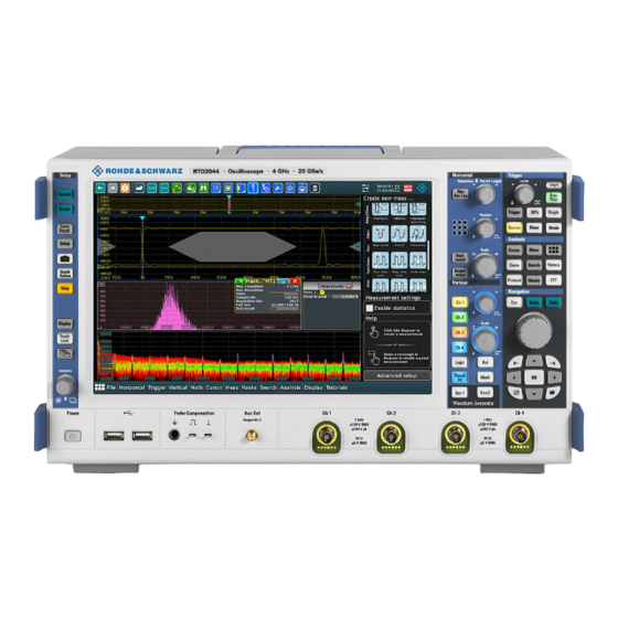
® Instrument tour R&S RTO2000 Front panel Instrument tour This chapter describes the front and rear panels of the instrument including all function keys and connectors. Front panel The front panel of the R&S RTO is shown in Figure 5-1. The function keys are grouped in functional blocks to the left and the right of the touchscreen. - Page 27 ® Instrument tour R&S RTO2000 Front panel 5 = [Analysis] keys 6 = [Navigation] controls 7 = [Waveform Generator] keys 8 = [Vertical] controls 9 = Input channels 10 = [Aux Out] connector 11 = Connectors for probe compensation and grounding...
-
Page 28: Rear Panel
® Instrument tour R&S RTO2000 Rear panel Square wave signal for probe compensation, 1 kHz and 1 V Ground connector for probes. [Aux Out] Output of the internal calibration signal, if the signal is configured to external des- tination. Rear panel Figure 5-2 shows the rear panel of the R&S RTO. - Page 29 ® Instrument tour R&S RTO2000 Rear panel 9 = Option slot for R&S RTO-B1 (MSO, shown in figure) or R&S RTO-B1E (for R&S RT-ZVC) , or R&S RTO-B10 (GPIB) 10 = External trigger input 11 = Optional OCXO with input and output of the reference signal (option R&S RTO-B4) 12 = Kensington lock slot to secure the instrument against theft 13 = Optional exchangeable hard disk: solid state disk (option R&S RTO-B18) or standard hard...
- Page 30 ® Instrument tour R&S RTO2000 Rear panel DVI-D Digital connector for an external monitor or projector. The monitor shows the com- plete content of the instrument's screen. Ext Trigger In The BNC connector for external trigger input is used to control the measurement by an external signal.
-
Page 31: Keys And Controls
® Instrument tour R&S RTO2000 Keys and controls OCXO option R&S RTO-B4 Optional [Ref In] (left) and [Ref Out] (right) connectors coming with option R&S RTO-B4 OCXO 10 MHz. The input frequency ranges from 1 MHz to 20 MHz in 1 MHz steps. The input impedance is 50 Ω. - Page 32 ® Instrument tour R&S RTO2000 Keys and controls The light of the key shows the instrument state: ● Standby, the main power switch is on, the software is shut down: orange. ● The instrument is ready for operation: green. See also: Chapter 4.7, "Switching on or...
- Page 33 ® Instrument tour R&S RTO2000 Keys and controls Camera Starts a saving action, or opens a report. By default, the key saves a screenshot of the waveform display. You can assign the function to the key. Quick Action Starts an external application, opens the graphical recall, or deletes the all mea- surement results, waveforms, and the history.
- Page 34 ® Instrument tour R&S RTO2000 Keys and controls [Res Rec Len], [Horizontal] Open and close the "Setup" tab in the "Horizontal" dialog box, where you can: ● Adjust the time scale, and acquisition time ● Adjust the horizontal position, and reference point ●...
- Page 35 ® Instrument tour R&S RTO2000 Keys and controls You can select if the knob changes the position or the reference point in "File" menu > "Frontpanel Setup" > "Knobs". To set the value to zero, press the knob. The current value is shown in the input box in the lower right corner of the screen.
- Page 36 ® Instrument tour R&S RTO2000 Keys and controls [Ch <n>] Turns on, selects, and configures a channel. If the channel is active, the key lights up in the corresponding channel color . The effect of the keypress depends on state of the channel: ●...
- Page 37 ® Instrument tour R&S RTO2000 Keys and controls [Scale] This rotary knob adjusts the vertical scale for the selected waveform. The knob lights up in the color of the selected waveform. Turn clockwise to stretch the waveform. Doing so, the scale value V/div decrea- ses.
- Page 38 ® Instrument tour R&S RTO2000 Keys and controls [Source] Opens a dialog box where you can select the trigger source. Press the key again to switch the source. The key lights up in the color of the selected trigger source.
- Page 39 ® Instrument tour R&S RTO2000 Keys and controls [Cursor] Displays vertical and horizontal cursors in the active diagram and opens the "Cur- sor Results" box. Cursors are markers which are placed at points of interest on a waveform. The instrument measures the cursor positions and delta values between parallel cur- sors.
- Page 40 ® Instrument tour R&S RTO2000 Keys and controls [Search] Opens and closes the "Search" dialog box, where you can: ● Configure trigger events to be searched for ● Limit the search by gating ● Configure the presentation of search results [Masks] Opens and closes the "Masks"...
- Page 41 ® Instrument tour R&S RTO2000 Keys and controls [Navigation] rotary knob The [Navigation] knob has various functions: ● In numeric entry fields: turn to increase or decrease the value. ● In tables: press to activate the edit mode, turn clockwise to increase the value or turn counterclockwise to decrease it, and press to enter the value and move to the next cell.
- Page 42 ® Instrument tour R&S RTO2000 Keys and controls ● In tables: the key activates the edit mode. If the table cell is in edit mode, the key confirms the value, quits the edit mode and moves to the next cell.
-
Page 43: Operating The Instrument
® Operating the instrument R&S RTO2000 Means of manual interaction Operating the instrument There are three ways to operate the R&S RTO. Manual operation Use the touchscreen, keys and rotary knobs, or an optional mouse and/or key- board. The principles of manual operation are explained in this section. -
Page 44: Touchscreen Display
® Operating the instrument R&S RTO2000 Touchscreen display Using the touchscreen is the direct interaction way. Use your finger to place waveforms on the screen, mark areas for zoom and histograms, set parame- ters in dialog boxes, enter data, and much more. The control elements and actions on the screen are based on common concepts, and you will easily become familiar with the user interface. - Page 45 ® Operating the instrument R&S RTO2000 Touchscreen display Figure 6-1: Display information 1 = Diagram 2 = Grid 3 = Trigger position 4 = Reference point (distance from trigger position to reference point = horizontal position) 5 = Trigger, horizontal and acquisition label...
- Page 46 ® Operating the instrument R&S RTO2000 Touchscreen display By default, the diagram name contains the diagram number and the short names of the waveforms shown inside. To change the diagram name, touch and hold the tab name. The on-screen keyboard opens to enter the new name. Names must be unique.
- Page 47 ® Operating the instrument R&S RTO2000 Touchscreen display Figure 6-3: Horizontal label on the toolbar 1 = Time scale 2 = Horizontal position Figure 6-4: Acquisition label on the toolbar 1 = Sample rate 2 = Record length 3 = Decimation...
- Page 48 ® Operating the instrument R&S RTO2000 Touchscreen display As for waveform diagrams, you can change the name of the zoom diagram. A zoom in a zoom and coupled zooms are also possible. All zooming possibilities are described in detail in the user manual, chapter "Zoom".
- Page 49 ® Operating the instrument R&S RTO2000 Touchscreen display Histogram and histogram area A histogram shows the frequency of occurrence of voltage or time values in a bar chart directly in the diagram. The rectangular histogram area indicates the part of the waveform that is considered in the histogram.
- Page 50 ® Operating the instrument R&S RTO2000 Touchscreen display = Toolbar = Tab in a dialog box = Dialog box = Result table (docked) = Signal bar = Menu Not shown = Input box Toolbar (1) The icons on the toolbar provide quick and easy access to the most important functionality.
-
Page 51: App Cockpit
® Operating the instrument R&S RTO2000 App cockpit Input box The input box appears if you adjust a value using one of the rotary knobs, or if you drag an element on the screen, for example, a cursor line. The input box shows the current value of the modified parameter. -
Page 52: Working With Waveforms
® Operating the instrument R&S RTO2000 Working with waveforms Working with waveforms The R&S RTO can create and display many waveform types. The most importand are: ● Channel waveforms: Up to three waveforms per input channel can be shown. For a four-channel instrument, 12 channel waveforms are available. - Page 53 ® Operating the instrument R&S RTO2000 Working with waveforms Show the details of waveforms. ● XY-waveforms: Four XY-waveforms can be created. Each XY-waveform is built from the volt- age values of two source waveforms. ● Digital waveforms: The Mixed Signal Option R&S RTO-B1 provides 16 digital channels grouped in two logic probes (pods) with 8 channels each.
- Page 54 ® Operating the instrument R&S RTO2000 Working with waveforms The vertical [Position] and the [Scale] knobs are illuminated with the color of the selected waveform. Figure 6-1, C1 is the selected waveform: The frame of the diagram and the signal icon are highlighted.
-
Page 55: Rohde & Schwarz Smartgrid
® Operating the instrument R&S RTO2000 Rohde & Schwarz smartgrid To switch off a waveform ► Do one of the following: ● Select the waveform, and then press the [Signal Off] key. ● To switch off a minimized waveform, tap the "Close" icon in the upper right corner of the minimized signal view. -
Page 56: Toolbar
® Operating the instrument R&S RTO2000 Toolbar To arrange a waveform using the SmartGrid You can arrange waveforms in one of the existing diagrams, or in a new diagram. 1. Drag the signal icon to the diagram area, and move it around. - Page 57 ® Operating the instrument R&S RTO2000 Toolbar By default, the toolbar shows the most frequently used functions. You can config- ure the content of the toolbar, see Chapter 6.6.2, "Configuring the toolbar", on page 58. 6.6.1 Using the toolbar Using the toolbar is easy and straightforward.
- Page 58 ® Operating the instrument R&S RTO2000 Toolbar ● Tap the required diagram. ● Drag a rectangle on the diagram. 6.6.2 Configuring the toolbar You can configure the content of the toolbar so that only the required functions are displayed. Furthermore, date and time can be hidden. The toolbar configura- tion is part of the user preferences.
- Page 59 ® Operating the instrument R&S RTO2000 Toolbar One-click actions Interactive actions Undo Zoom Redo Search Help Cursor Graphical Saveset Mask Test Saveset Histogram Image Measure Report Quick meas Clear Autoset and Preset Label Run / Stop and Single Save Reference...
- Page 60 ® Operating the instrument R&S RTO2000 Toolbar One-click actions Interactive actions Force Trigger Zone trigger Demo Spectrogram (option R&S RTO-K18) You can configure the content of the toolbar, see Chapter 6.6.2, "Configuring toolbar", on page 58. The following list describes at first the default toolbar functions and then the addi- tional functions.
- Page 61 ® Operating the instrument R&S RTO2000 Toolbar Image Saves a screenshot of the current display using the settings defined in "Menu" >"Save/Recall" > "Save" tab > "Screenshot". Report Creates a report of the current measurement settings and results using the settings defined in "Menu"...
- Page 62 ® Operating the instrument R&S RTO2000 Toolbar To use another zoom type, select it in the toolbar assist. Standard zoom ← Zoom Displays a magnified section of the diagram in an additional zoom diagram. It is a display zoom, instrument settings are not changed.
- Page 63 ® Operating the instrument R&S RTO2000 Toolbar Cursor The cursor icon shows the last selected cursor type. A short tap on the icon activates the selected cursor. To use another cursor type, select it in the toolbar assist, and adjust the settings.
- Page 64 ® Operating the instrument R&S RTO2000 Toolbar To modify the measurement, double-tap one of the result values. Quick meas Performs a set of measurements on the selected waveform or on the selected gate. You can configure up to 8 measurements to be included in quick measurement.
-
Page 65: Displaying Results
® Operating the instrument R&S RTO2000 Displaying results Zone trigger Defines a zone trigger, which combines the trigger condition with the inter- section or non-intersection of one or more zones or masks. Tap the icon and then tap the corner points of the zone on the screen. Tap "Finish zone". - Page 66 ® Operating the instrument R&S RTO2000 Displaying results ● Automatic measurements: select "Measurement" tab > "Result position". ● Cursor measurements: select "Cursor" tab > "Result position". ● Protocols: select "Protocol" tab > "Result position". To arrange the results on the display 1.
-
Page 67: Using Dialog Boxes
® Operating the instrument R&S RTO2000 Using dialog boxes To open the corresponding setup dialog box 1. Double-tap one of the result values. If a result box is shown, you can also tap the icon. 2. In the toolbar assist, tap "Advanced Setup" . -
Page 68: Entering Data
® Operating the instrument R&S RTO2000 Entering data ● Open the "Menu", and select the menu entry. ● Press the function key on the front panel. ● Double-tap a result icon, or tap the icon in a result box to open the cor- responding dialog box. - Page 69 ® Operating the instrument R&S RTO2000 Entering data Using scale, position and level knobs The instrument has dedicated rotary knobs to set vertical and horizontal positions and scale, and the trigger level. When you turn a knob, the input box appears in the lower right corner of the screen, showing the parameter name and current value.
- Page 70 ® Operating the instrument R&S RTO2000 Entering data 2. Enter the numeric value using the following methods: ● To use the default value, tap "Reset" (if available). ● To use the minimum or maximum value, tap "Min" or "Max", respectively.
-
Page 71: Instrument Information And Notifications
® Operating the instrument R&S RTO2000 Instrument information and notifications 2. Enter the text as you would on a normal keyboard. ● To enter a series of capital characters, tap "Caps". To enter one capital character, tap "Shift". ● To use the currently defined value, tap "Cur". This is the value that was used before the keyboard was displayed. -
Page 72: Getting Information And Help
® Operating the instrument R&S RTO2000 Getting information and help ► To see the instrument information, tap the Rohde & Schwarz logo. Notifications are status messages, information on mismatching settings and simi- lar information. They are displayed for a few seconds and saved. - Page 73 ● The general help opens the help window with a table of contents, where you can browse and search for information. ● Videos explain various analyzing and measurement tasks. They are available in the R&S®RTO2000 - Media Center. 6.11.1 Displaying help To display tooltips and context help 1.
- Page 74 ® Operating the instrument R&S RTO2000 Getting information and help ● "Contents" - contains a table of help contents ● "Index" - contains index entries to search for help topics ● "Search" - provides text search The Help toolbar provides some buttons: ●...
- Page 75 ® Operating the instrument R&S RTO2000 Getting information and help "trigger qualification". A search for trigger qualification finds all topics that contain the words trigger and qualification. ● Use "Match whole word" and "Match case" to refine the search. ● Use operators AND, OR, and NOT.
-
Page 76: Setting Up The Instrument
® Setting up the instrument R&S RTO2000 Performing a self-alignment Setting up the instrument Basic setup procedures for the instrument are the following: ● Performing a self-alignment................76 ● Setting the display language................77 ● Adjusting passive probes................77 Performing a self-alignment The self-alignment aligns the data from several input channels vertically and hori- zontally to synchronize the timebases, amplitudes and positions. -
Page 77: Setting The Display Language
® Setting up the instrument R&S RTO2000 Adjusting passive probes Setting the display language You can change the language in which the dialog boxes, result boxes and other screen information is displayed. A reboot of the instrument is not necessary. - Page 78 ® Setting up the instrument R&S RTO2000 Adjusting passive probes Getting Started 1332.9719.02 ─ 11...
-
Page 79: Contacting Customer Support
® Contacting customer support R&S RTO2000 Contacting customer support Technical support – where and when you need it For quick, expert help with any Rohde & Schwarz product, contact our customer support center. A team of highly qualified engineers provides support and works with you to find a solution to your query on any aspect of the operation, program- ming or applications of Rohde &... -
Page 80: Index
® Index R&S RTO2000 Index Dialog boxes ..........49 Background transparency ....33 Acquisition Usage ..........67 Key ............34 Digital waveforms ........52 Single, multiple ........38 Display Start ............ 38 Key ............33 Stop ............ 38 Overview ..........44 Active waveform ........53... - Page 81 ® Index R&S RTO2000 Histograms ..........63 MSO ............30 Area ............ 49 Diagram ..........49 History key ..........40 Navigation controls Horizontal Data input ........... 71 Controls ..........33 Keys ............ 42 Key ............34 Overview ..........40 Label ........... 48 Normal trigger mode ........38...
- Page 82 ® Index R&S RTO2000 Rack mounting ........19 Signal Off key .......... 37 Record length Signal view ..........48 Rotary knob ........34 Single ............61 Redo ............60 Single key ..........38 Key ............41 Slope Ref key ............ 36 Key ............38...
- Page 83 ® Index R&S RTO2000 Touchscreen Switch off ..........55 Compared with mouse ......43 Switch on ..........54 Control elements .........49 XY ............52 Lock, unlock ........33 Zoom ...........52 Usage ..........43 Web interface .......... 43 Transparency ...........33 Windows Trigger Access ..........
Need help?
Do you have a question about the RTO2000 and is the answer not in the manual?
Questions and answers