Danfoss H1P 147 Manuals
Manuals and User Guides for Danfoss H1P 147. We have 3 Danfoss H1P 147 manuals available for free PDF download: Service Manual, Technical Information
Danfoss H1P 147 Service Manual (68 pages)
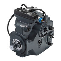
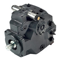
Axial Piston Single Pumps
Brand: Danfoss
|
Category: Water Pump
|
Size: 9 MB
Table of Contents
Advertisement
Danfoss H1P 147 Service Manual (67 pages)
Axial Piston Single Pumps
Brand: Danfoss
|
Category: Water Pump
|
Size: 12 MB
Table of Contents

Danfoss H1P 147 Technical Information (64 pages)
Axial Piston Single Pumps Size 147/165
Brand: Danfoss
|
Category: Water Pump
|
Size: 9 MB
Table of Contents
Advertisement
Advertisement