
Related Manuals for Danfoss H1 45


Summary of Contents for Danfoss H1 45
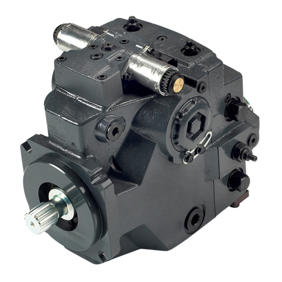
- Page 1 MAKING MODERN LIVING POSSIBLE Repair Instructions Closed Circuit Axial Piston Pumps H1 45/53/60/68 powersolutions.danfoss.com...
- Page 2 Repair Instructions H1 45/53/60/68 Closed Circuit Axial Piston Pumps Revision history Table of revisions Date Changed September 2014 add MDC control March 2014 Danfoss Layout March 2013 Control topic titles - to be more generic June 2011 add protection shield for automotive control...
-
Page 3: Table Of Contents
Repair Instructions H1 45/53/60/68 Closed Circuit Axial Piston Pumps Contents Introduction Overview......................................5 General Instructions..................................5 Remove the unit..................................5 Keep it clean....................................5 Lubricate moving parts................................5 Replace all O-rings and gaskets............................. 5 Secure the unit..................................... 6 Safety Precautions....................................6 Unintended machine movement............................6 Flammable cleaning solvents.............................. - Page 4 Repair Instructions H1 45/53/60/68 Closed Circuit Axial Piston Pumps Contents Servo Piston Installation................................32 Servo Cylinder Installation................................33 Cylinder Kit Assembly...................................34 Cylinder Kit Installation................................35 Timing Pin and Endcap Bushing Installation........................35 Endcap Bushing Installation tools............................36 Endcap Bushing Orientation..............................36 Valve Plate and Endcap Installation............................37 Charge Pump Installation................................
-
Page 5: Overview
Where rework of worn or damaged components is possible, specifications appear to ensure these parts meet factory tolerances. Only Danfoss Global Service Partners (GSPs) are authorized to perform major repairs. Danfoss trains Global Service Partners and certifies their facilities on a regular basis. -
Page 6: Secure The Unit
Repair Instructions H1 45/53/60/68 Closed Circuit Axial Piston Pumps Introduction Secure the unit For major repair, place the unit in a stable position with the shaft pointing downward. It is necessary to secure the pump while removing and torquing the endcap bolts. -
Page 7: Symbols Used In Danfoss Literature
Repair Instructions H1 45/53/60/68 Closed Circuit Axial Piston Pumps Introduction Symbols used in Danfoss literature WARNING may result in injury Tip, helpful suggestion CAUTION may result in damage to product or Lubricate with hydraulic fluid property Reusable part Apply grease / petroleum jelly... -
Page 8: Disassembly
Repair Instructions H1 45/53/60/68 Closed Circuit Axial Piston Pumps Disassembly Shaft Seal Removal 1. Orient pump with the shaft pointing up. 2. Remove the spiral ring (J300) from the front housing to release the shaft seal carrier (J275). 3. Pry on the lip of the seal carrier to remove it from the pump. -
Page 9: Control Removal
Repair Instructions H1 45/53/60/68 Closed Circuit Axial Piston Pumps Disassembly 3. Use an adequate press to remove the bearing from the shaft. Control Removal 1. Remove control screws (D250) using a 5 mm internal hex wrench. Remove the control from the pump 2. -
Page 10: Control Disassembly
Repair Instructions H1 45/53/60/68 Closed Circuit Axial Piston Pumps Disassembly Control Disassembly If you suspect a coil malfunction, remove the coil. Remove the plastic nut with a 26 mm 12 point socket. Install a new coil. Torque nut to 5 N•m [3.7 lbf•ft]. -
Page 11: Auxiliary Pad Or End Cover Removal
Repair Instructions H1 45/53/60/68 Closed Circuit Axial Piston Pumps Disassembly Special Plug tool Drill out retention ring Screen Retention Ring 45 deg. Ø 9.22 mm Ø 14 mm Ø 1.7 mm (x3) P108021 Remove control Security wax seal (2X) D610 (2X) -
Page 12: Charge Pump Removal
Repair Instructions H1 45/53/60/68 Closed Circuit Axial Piston Pumps Disassembly 4. Remove thrust washer (K500). Note thrust washer orientation. 5. Remove pressure balance plate (S200) and seal (S300). Note plate orientation. Discard seal (S300). 6. Remove coupling (K200). Remove end cover and charge pump... -
Page 13: Pressure Limiter Removal
Repair Instructions H1 45/53/60/68 Closed Circuit Axial Piston Pumps Disassembly Auxilliary pads K400 8 mm SAE B SAE A E101 533E Pressure Limiter Removal 1. Using a 14 mm wrench, remove pressure limiter cartridges (L300) and (L400). Pressure limiter (L300 / L400) is available as complete unit only. Seal (L022) is available separately. -
Page 14: High Pressure Relief Valve Removal
Repair Instructions H1 45/53/60/68 Closed Circuit Axial Piston Pumps Disassembly Remove charge pressure relief valve V024 22 mm E101 407E High Pressure Relief Valve Removal Using a 22 mm wrench, remove the HPRV valves (L100 / L200). Discard O-rings (L060) and seals (L068). -
Page 15: Cylinder Block Kit Removal
Repair Instructions H1 45/53/60/68 Closed Circuit Axial Piston Pumps Disassembly Remove endcap and components G350 (4X) 10 mm G400 (2X) 10 mm G100 C020 G550 C025 G150 B010 B010 B040 (2x) E101 408E Cylinder Block Kit Removal 1. Remove cylinder block assembly (C010). -
Page 16: Servo Sleeve Removal
Repair Instructions H1 45/53/60/68 Closed Circuit Axial Piston Pumps Disassembly Remove cylinder block kit C010 E101 409E Servo Sleeve Removal 1. If equipped with displacement limiter, remove and discard locking nut (E550) and remove displacement limiter screw (E450). 2. Remove the locking screws (E350) with a 10 mm hex wrench. Remove the locking plates (E300). -
Page 17: Servo Piston Removal
Repair Instructions H1 45/53/60/68 Closed Circuit Axial Piston Pumps Disassembly Remove servo cylinders E250 E600 E300 E101 410E E350 10 mm Servo Piston Removal Tilt swashplate up to disengage servo arm from piston. Remove the servo piston assembly (E100). Remove servo piston... -
Page 18: Servo Piston Disassembly
Repair Instructions H1 45/53/60/68 Closed Circuit Axial Piston Pumps Disassembly Remove swashplate and swashplate bearings D070 (060/068) D075 (045/053) D075 (045/053) D070 (060/068) D070 045/053 old style swashplate bearing If pump with old style bearing is being repaired; discard old style bearing, and replace with new E101 412E style bearing. -
Page 19: Cylinder Kit
Repair Instructions H1 45/53/60/68 Closed Circuit Axial Piston Pumps Disassembly Cylinder Kit Disassemble the cylinder block kit 1. Pull to remove the slipper retainer (C20) with the pistons (C10) from the cylinder kit. The pistons are not selectively fitted, however units with high hourly usage may develop wear patterns. - Page 20 Repair Instructions H1 45/53/60/68 Closed Circuit Axial Piston Pumps Disassembly Disassemble cylinder block kit E101 395E 520L0957 • Rev CB • September 2014...
-
Page 21: Inspection
Repair Instructions H1 45/53/60/68 Closed Circuit Axial Piston Pumps Inspection Overview Wash all parts (including the endcap and housing) thoroughly with clean solvent and allow to air dry. Blow out oil passages in the housing and endcap with compressed air. Conduct inspection in a clean area and keep all parts free from contamination. -
Page 22: Cylinder Block
Repair Instructions H1 45/53/60/68 Closed Circuit Axial Piston Pumps Inspection Inspect block spring and washers Washer Cylinder block spring Spring retainer Retaining ring P101 472 Cylinder Block Examine the running face of the cylinder block. The surface should be smooth and free of nicks and burrs. -
Page 23: Swashplate
Repair Instructions H1 45/53/60/68 Closed Circuit Axial Piston Pumps Inspection Inspect shaft bearing E101 376E Swashplate Carefully inspect each machined surface of the swashplate for wear. Ensure all swashplate surfaces are smooth. Inspect the swashplate's slipper running surface for flatness and brass transfer. Excessive brass transfer from slippers may indicate you should replace the slippers. -
Page 24: Endcap
Repair Instructions H1 45/53/60/68 Closed Circuit Axial Piston Pumps Inspection Inspect valve plate Clockwise valveplate Counterclockwise valveplate P108 061E Endcap Inspect the endcap. Inspect all machined surfaces for scratches or pits. Carefully check the bearing surface for wear.Inspect valve seats carefully for wear or cracks.Replace if damaged. -
Page 25: Pressure Limiter
Repair Instructions H1 45/53/60/68 Closed Circuit Axial Piston Pumps Inspection Inspect housing E101 413E Pressure Limiter Pressure limiter valves are available as complete units only. If you suspect valve malfunction, replace the valve(s) and test pump operation. Replace O-rings before reassembly. -
Page 26: Cradle Bearings
Repair Instructions H1 45/53/60/68 Closed Circuit Axial Piston Pumps Inspection Pressures marked on HPRV valve (continued) Code Pressure bar [psi] 350 [5076] 380 [5511] 400 [5801] Inspect HPRV valve Pressure code marked on end P106 662E Cradle Bearings Inspect the cradle bearings for damage or excessive wear. Slide the bearings by hand and feel for roughness. -
Page 27: Charge Pressure Relief Valve
Repair Instructions H1 45/53/60/68 Closed Circuit Axial Piston Pumps Inspection Inspect displacement limiter P106 131E Charge Pressure Relief Valve Charge pressure relief valve is available as a complete unit only. If you suspect valve malfunction, replace the valve and test pump operation. Replace O-rings before assembly. -
Page 28: Control
Repair Instructions H1 45/53/60/68 Closed Circuit Axial Piston Pumps Inspection Inspect servo assembly P101 337E Control Inspect sealing surfaces of control. If you find nicks or scratches that may allow fluid leakage, replace control. Inspect feedback spring and linkage. Control is available as a complete unit only. If you suspect control operation problems, replace control with a new unit and test pump. -
Page 29: Assembly
Assembly Overview The following section describes assembly procedures for the H1 45/53 pump. If special tools are needed for assembly or adjustment, they appear in this section. After assembly, adjust the pump according to the settings listed on the model code stamped on the serial number plate. Connect the pump to an appropriate test stand. -
Page 30: Cradle Bearings And Swashplate Installation
Repair Instructions H1 45/53/60/68 Closed Circuit Axial Piston Pumps Assembly Positioning seal in seal carrier Press flush to this surface +0.12 mm [ 0.005 in] / -0.72 mm [ 0.028 in] Seal P106 498E 4. Install the shaft assembly into the front housing. Cover the shaft with an installation sleeve to protect it during installation of the seal carrier. - Page 31 Repair Instructions H1 45/53/60/68 Closed Circuit Axial Piston Pumps Assembly Install cradle bearings and swashplate D070 (060-068) D075 (045-053) D075 (045-053) D070 (060-068) D070 B040 045-053 E101 414E Old style swashplate bearing If pump with old style bearing is being repaired;...
-
Page 32: Servo Piston Assembly
Repair Instructions H1 45/53/60/68 Closed Circuit Axial Piston Pumps Assembly Servo Piston Assembly 1. Lubricate and install new piston seals and O-rings (E025). Stretch O-rings onto servo piston, then install piston seals outboard of the O-rings. Allow seals to relax before installing servo piston. Use the servo cylinder to resize the seals before installing servo piston. -
Page 33: Servo Cylinder Installation
Repair Instructions H1 45/53/60/68 Closed Circuit Axial Piston Pumps Assembly Install servo piston E100 E101 411E Servo Cylinder Installation 1. Lubricate new O-rings (E250) and install on each servo cylinder. 2. While holding the servo piston in place, thread servo cylinders into housing using a 3/4 in socket. -
Page 34: Cylinder Kit Assembly
Repair Instructions H1 45/53/60/68 Closed Circuit Axial Piston Pumps Assembly After pump assembly is complete, mount pump on test stand. Perform mechanical neutral adjustment and control neutral adjustment. Refer to H1 Closed Circuit Axial Piston Pumps 045/053/060/068 Service Manual 520L0958 for adjustment procedures. -
Page 35: Cylinder Kit Installation
Repair Instructions H1 45/53/60/68 Closed Circuit Axial Piston Pumps Assembly Be sure to install the slipper retainer (C20) so it mates correctly with the ball guide (C15) (concave side of the slipper retainer against the convex side of the ball guide). -
Page 36: Endcap Bushing Installation Tools
Repair Instructions H1 45/53/60/68 Closed Circuit Axial Piston Pumps Assembly Install bushings in endcap Bushing installation tool Installation depth 2.1mm ±0.25mm [0.083 in ±0.01in] G550 P106 495E Endcap Bushing Installation tools Bushing installation tool Go, No-Go gauge Must be greater than Installation depth 2.1mm ±0.25mm... -
Page 37: Valve Plate And Endcap Installation
Repair Instructions H1 45/53/60/68 Closed Circuit Axial Piston Pumps Assembly Valve Plate and Endcap Installation 1. Install the alignment pins (B010) in housing. 2. Clean the valve plate (C025) and endcap (G100). For proper pump operation, it is extremely important to ensure that there is no contamination between the endcap and valve plate. -
Page 38: Charge Pump Installation
Repair Instructions H1 45/53/60/68 Closed Circuit Axial Piston Pumps Assembly P106 230E Valveplate orientation Clockwise v a lveplate Counterclockwise v alveplate Notch used for EDC or FNR controls Notch used for NFPE or AC controls P108 060E Charge Pump Installation Charge pump components are available as a complete kit only. -
Page 39: Auxiliary Pad Or End Cover Installation
Repair Instructions H1 45/53/60/68 Closed Circuit Axial Piston Pumps Assembly Remove end cover and charge pump K500 S300 S200 K200 S100 S250 S300 E101 423E Auxiliary Pad or End Cover Installation 1. Install alignment pins (G450). Install gasket (K150). 2. Install end cover or auxiliary pad with cap screws (K400) using an 10 mm internal hex wrench. Torque to 92 N•m [68 lbf•ft]. -
Page 40: Charge Pressure Relief Valve Installation
Repair Instructions H1 45/53/60/68 Closed Circuit Axial Piston Pumps Assembly End cover K400 8 mm 92 N•m [68 lbf•ft] K100 G450 G450 K150 P106 684E Torque sequence P106 346E Auxilliary pads K400 K400 8 mm 8 mm 92 Nm 92 Nm [68 lbf•ft]... -
Page 41: Pressure Limiter Installation
2. Using a 14 mm wrench, install pressure limiter cartridges (L300) and (L400). 3. Torque to 30 N•m [22 lbf•ft]. Refer to Danfoss publication H1 45/53/60/68 Closed Circuit Axial Piston Pumps Service Manual 520L0958 for instructions on adjusting pressure limiter. -
Page 42: Optional Displacement Limiter Installation
2. Thread a new locking nut onto adjustment screw. Torque to 23 N•m [17 lbf•ft] using a 13mm hex wrench. Refer to Danfoss publication H1 45/53/60/68 Closed Circuit Axial Piston Pumps Service Manual 520L0958 for instructions on adjusting displacement limiter. -
Page 43: Control Assembly
Repair Instructions H1 45/53/60/68 Closed Circuit Axial Piston Pumps Assembly Displacement limiter adjustment data (continued) Displacement Locknut wrench size and Adjusting screw Approximate displacement change torque size per revolution of adjusting screw 13 mm 23 N•m [17 lbf•ft] 4 mm internal hex 7.7 cm... -
Page 44: Control Installation
Repair Instructions H1 45/53/60/68 Closed Circuit Axial Piston Pumps Assembly Control Installation Install the control D250 (6X) 5 mm D084 D150 D200 D300 (2X) P108776 Torque sequence P106 231E P106 231E 1. Install feedback spool into housing. Carefully engage the spool in the swashplate 2. - Page 45 Repair Instructions H1 45/53/60/68 Closed Circuit Axial Piston Pumps Assembly Removal Refer to exploded diagram, below. 1. Using a 5 mm internal hex wrench, remove the six cap screws (D250). 2. Remove the control module and gasket (D150). Discard the gasket.
- Page 46 Repair Instructions H1 45/53/60/68 Closed Circuit Axial Piston Pumps Assembly MDC illustration - single pumps MDC with CCO D250 D065 D692 D065 D250 D693 D750 D735 D084 D098 F00T MDC with neutral start switch D250 D065 D150 D200 D300 (2X)
-
Page 47: Reassembly
Repair Instructions H1 45/53/60/68 Closed Circuit Axial Piston Pumps Assembly MDC Legend - single pumps Wrench size and torque Item Description Wrench size Torque D065 O-ring plug 3/16 internal hex 12 N•m [9 lbf•ft] D084 screen D098 ring D200 feedback pin 13 mm deep well socket 22.5-27.5 Nm [16.6-20.3 lbf•ft]... -
Page 48: Automotive Control Installation
Repair Instructions H1 45/53/60/68 Closed Circuit Axial Piston Pumps Assembly Remove the plug on top of the control to ensure the swashplate feedback pin is properly positioned in the center of the control module when installing control. 5. Install the control module and six cap screws (D250). - Page 49 Repair Instructions H1 45/53/60/68 Closed Circuit Axial Piston Pumps Assembly Install control Security wax seal (2X) 13.3 Nm [9.8 lbf•ft] D610 (2X) D250 5 mm D672 (6X) D674 D084 D640 D098 2.5 Nm [1.8 lbf•ft] F00A D150 3 mm F00B...
-
Page 50: Startup Procedures
H1 45/53/60/68 Closed Circuit Axial Piston Pumps Startup procedures Overview Install pump on test stand. Refer to H1 45/53/60/68 Closed Circuit Axial Piston Pumps Service Manual 520L0958 for startup procedures, adjustments, and pressure measurements for H1 45/53/60/68 pump. Initial Startup Procedures •... -
Page 51: Port Locations And Gauge Installation
Repair Instructions H1 45/53/60/68 Closed Circuit Axial Piston Pumps Port locations Port Locations and Gauge Installation The following table and drawing show the port locations and gauge sizes needed. When testing system pressures, calibrate pressure gauges frequently to ensure accuracy. Use snubbers to protect gauges. -
Page 52: Torque Chart
Repair Instructions H1 45/53/60/68 Closed Circuit Axial Piston Pumps Torque chart Fastener Size and Torque Chart Item Fastener Wrench size Torque D015 Neutral adjust screw 4 mm internal hex D050 Coil mounting bolt 4 mm internal hex 8 N•m [9 lbf•ft]... -
Page 53: Fasteners And Plugs
Repair Instructions H1 45/53/60/68 Closed Circuit Axial Piston Pumps Torque chart Fasteners and Plugs L200 High pressure relief valve V020 Charge pressure adjusting screw V022 Charge pressure locking nut Charge pressure K400 cartridge Rear cover / auxiliary pad mounting bolt... - Page 54 Repair Instructions H1 45/53/60/68 Closed Circuit Axial Piston Pumps 520L0957 • Rev CB • September 2014...
- Page 55 Repair Instructions H1 45/53/60/68 Closed Circuit Axial Piston Pumps 520L0957 • Rev CB • September 2014...
- Page 56 Phone: +86 21 3418 5200 Danfoss can accept no responsibility for possible errors in catalogues, brochures and other printed material. Danfoss reserves the right to alter its products without notice. This also applies to products already on order provided that such alterations can be made without changes being necessary in specifications already agreed.
Need help?
Do you have a question about the H1 45 and is the answer not in the manual?
Questions and answers