
Subscribe to Our Youtube Channel
Related Manuals for B-TEK Scales 4 Square


Summary of Contents for B-TEK Scales 4 Square
- Page 1 4 Square Workhorse Models Include: Clydesdale Drum Scale Clydesdale Lift Deck RPS (Rocker Pin)
- Page 2 2020 Floor Scale Installation Manual www.B-TEK.com...
-
Page 3: Table Of Contents
Contents Introduction Page 4 4 Square General Specs Page 5 Clydesdale Carbon General Specs Page 6 Clydesdale Stainless General Specs Page 7 Clydesdale Stainless Lift Deck General Specs Page 8 Workhorse Carbon General Specs Page 9 Drum Scale Carbon and Stainless General Specs General Specs... -
Page 4: Introduction
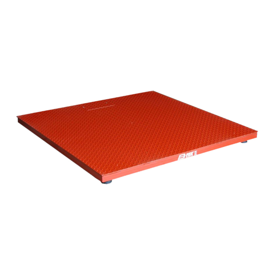
BS-SS-DS stainless steel Drum scale The 4 Square model of floor scale is a 4’ X 4’ platform with a NTEP approved capacity of 5,000 lbs. The Clydesdale series of carbon and stainless steel floor scale is available in standard platform sizes from 2’ X 2’ to 10’... -
Page 5: Square General Specs
4 Square Carbon Steel Floor Scale General Specifications: Certificate of Conformance: 94-092A4 Above ground or pit Type: 5,000 lbs. Scale Capacity: 150% End Load Capacity: 3-1/2” nominal, adjustable Scale Height: 4’ x 4’ Available Sizes: Laser cut 3/16” carbon steel tread plate decking with structural channel sub-structure... -
Page 6: Clydesdale Carbon General Specs
Clydesdale Carbon Steel Floor Scale General Specifications: Certificate of Conformance: 94-092A4 Above ground or pit Type: 500 - 20,000 lbs. - NTEP Approved Capacities Scale Capacity: 80% for 2.5K capacity End Load Capacity: 100% for 5K to 20K capacities 4-3/8” nominal (2.5K - 10K-SE) adjustable Scale Height: 5-3/8”... -
Page 7: Clydesdale Stainless General Specs
Clydesdale Stainless Steel Floor Scale General Specifications: Certificate of Conformance: 94-092A4 Above ground or pit Type: 2,500 - 10,000 lbs. Scale Capacity: 80% for 2.5K capacity End Load Capacity: 100% for 5K to 20K capacities 4-3/8” nominal (2.5K - 10K-SE) adjustable Scale Height: 2’... -
Page 8: Clydesdale Stainless Lift Deck General Specs
Clydesdale Stainless Steel Lift Deck Floor Scale General Specifications: Certificate of Conformance: 94-092A4 Above ground or pit Type: 2,500 - 5,000 lb Scale Capacity: 80% for 2.5K capacity End Load Capacity: 100% for 5K capacity 4-3/8" nominal height, adjustable Scale Height: 3' x 3' - 4' x 6' - Custom sizes upon request Available Sizes: 1/4"... -
Page 9: Workhorse Carbon General Specs
Workhorse Carbon Steel Heavy Duty General Specifications: Certificate of Conformance: 18-061 Above ground or pit Type: 20,0000 x 5lb Scale Capacity: 30,000 x 10lb 40,000 x 10lb 100% for 20K and 40K capacities End Load Capacity: 66% for 30K capacity 9”... -
Page 10: Drum Scale Carbon And Stainless General Specs General Specs
Drum Scale Carbon & Stainless Steel General Specifications: Certificate of Conformance: 94-092A4 Low profile above ground Type: 1,000 & 2,500 lbs. Scale Capacity: 1-1/2” nominal deck height Scale Height: 2’ x 2’ - 4’ x 4’ - Custom sizes upon request Available Sizes: 1/4”... -
Page 11: Rocker Pin Suspension (Rps) Carbon And Stainless General Specs
Rocker Pin Suspension (RPS) Carbon & Stainless Steel General Specifications: Certificate of Conformance: 94-092A4 Above ground or pit Type: 1,000 x 0.2 lb Scale Capacity: 2,500 x 0.5 lb 5,000 x 1 lb 10,000 x 2 lb 3” nominal (1,000 - 5,000) Scale Height: 3-1/2”... -
Page 12: Installation Overview/Site Preperation
Installation Overview Prior to installation of the scale it is important to have the proper location and application for the particular scale being installed. The typical procedure for the installation of scales covered in this manual will consist of the following: •... -
Page 13: Pit Frame Installation
Optional Pit Frame Installation Instructions Cut out concrete 1’ larger than pit frame side (6” on each side) and dig out minimum of 8” deep. Note, you might need to cut larger area if the surrounding concrete is not level to make angled approach to the scale a gradual slope. Install 1”... -
Page 14: Unpacking
Unpacking Caution: The scale platform is heavy and can be awkward to handle. Exercise extreme care when lifting the scale platform to avoid personal bodily harm or damage to the equipment. Remove the packing material and inspect the scale for any visible damage occurring during shipment. -
Page 15: Assembling The Scale
Assembling the Scale Prior to installation of the scale the leveling feet must be threaded into the tapped through holes in each of the four load cells bolted to the corner assembly in the scale. In the case of a Workhorse heavy duty platform scale, four corner load cell assemblies with upper and possibly lower plates will need to be assembled and attached to the scale. -
Page 16: Assembling The Scale - Workhorse
Assembling the Scale - Workhorse Workhorse heavy duty platform scales need to have the leveling foot threaded into the load cell, then the top mounting plate will need to be attached to the scale weighbridge by four mounting bolts. The leveling foot may sit on the floor, may include foot locating plates, or may rest on topside of a bottom mounting plate, all depending on the application. -
Page 17: Assembling The Scale - Rps
Assembling the Scale - Rocker Pin Suspension Place base frame onto the floor making sure the frame is level. Install pins into all four corners. The rocker frame design does not allow for height adjustments. Temporarily place the scale onto the load pins to verify the scale does not rock from corner to corner. -
Page 18: Anchoring The Scale - Rps
Anchoring Rocker Pin Suspension Frame There are two anchor locations per corner. If shims are required, for additional height, place supplied shims under each corner. Drill 5/8” diameter hole, 2” into the cement. Do not ream or allow the drill to wobble. Repeat this step for all of the anchor locations. -
Page 19: Opening And Cleaning - Lift Deck
Opening and Cleaning - Lift Deck To open scale: Locate hand hole(s) and latch(es). Pull ring towards you to release locking bolt. Once all locking bolts are released lift deck. Once deck is open, locate built in locking/support bars. Locate built in upper clevis pin(s). Remove cotter pin and place support bar onto upper clevis pin. -
Page 20: Summing Board Connections
Summing Board Connections With the exception of the Workhorse, floor and drum scales are typically shipped with the load cells bolted in place and pre-wired to the summing board. Load cell wiring will be as follows for Sensortronic cells: Note: For alternate interchangeable load cell brands check calibration certificate for wiring specifics or refer to the drawing below. -
Page 21: Floor Scale Wiring Diagram
Floor Scale Wiring Diagram +EXC RED -EXC BLACK SHLD BLUE -SIG GREEN +SIG WHITE +EXC RED +EXC RED -SIG GREEN SHLD BLUE +SIG WHITE -EXC BLACK -EXC BLACK SHLD BARE & ORANGE +SEN BROWN -EXC BLACK -SEN BLUE +EXC RED +SIG GREEN -SIG WHITE 2020... -
Page 22: Connecting The Indicator
Connecting the Indicator Depending on the type of scale package and/or indicator purchased, the connecting or “homerun” cable between the scale and indicator may or may not be provided. A 4-wire cable is required to connect the two together, or an optional 6-wire cable for longer runs over 50 ft. -
Page 23: Troubleshooting
With all of the potentiometers at “maximum signal” set the test weight over one corner of the scale platform and record the weight shown on the indicator. Repeat this process for the remaining three corners. Whichever corner load cell has the lowest reading will be used as the reference and will not be adjusted. -
Page 24: Load Cell Replacement
Load Cell Replacement If a load cell should need replaced, verify the part number with the spare parts list in this manual. Replacement cells should be of the same capacity of the cell that is being replaced, as well as of the other cells in the scale. Lift the scale platform using lifting eyes, fork lift, or hydraulic jack. -
Page 25: Spare Parts
Spare Parts Part Number Item Notes 813-100018 500 lb load cell Nickel plated steel 813-100020 1,000 lb load cell Nickel plated steel 813-100021 2,500 lb load cell Nickel plated steel 813-100023 4,000 lb load cell Nickel plated steel 813-100025 5,000 lb load cell (SE) Nickel plated steel, small envelope 813-100024 5,000 lb load cell (LE) - Page 26 B-TEK Scales, LLC 1510 Metric Ave SW Canton, Ohio 44706 800.266.8900 • Direct: 330.471.8900 • Fax: 330.471.8909 Monday - Friday 7:00 AM - 5:00 PM www.B-TEK.com • sales@b-tek.com www.B-TEK.com Floor Scale Installation Manual 2016...
Need help?
Do you have a question about the 4 Square and is the answer not in the manual?
Questions and answers