Table of Contents
Advertisement
DD1010 Skynet Scale Setup
& Troubleshooting
BTEK
September
2021
This guide is intended to supplement and simplify other product technical manuals. The focus is
to instruct on setting up / troubleshooting the scale and communication ports on a DD1010
Skynet indicator. See Use, Maintenance, and Installation manual for overall product instruction,
and the start manual for features accessed during startup of the indicator.
Page | 1
Advertisement
Table of Contents

Related Manuals for B-TEK Scales DD1010


Summary of Contents for B-TEK Scales DD1010
- Page 1 This guide is intended to supplement and simplify other product technical manuals. The focus is to instruct on setting up / troubleshooting the scale and communication ports on a DD1010 Skynet indicator. See Use, Maintenance, and Installation manual for overall product instruction, and the start manual for features accessed during startup of the indicator.
-
Page 2: Table Of Contents
Table of Contents MAIN SCREEN ..............................4 Passwords ..............................4 Adding a Scale ............................... 5 Scale Metrological Seal ..........................6 Configuring Scales ............................7 Calibration Buttons ............................8 Scale Calibration............................9 Calibrating Analog Scale ..........................9 Calibrating Digital Scale........................... 10 Diagnostics .............................. - Page 3 Output connection ..........................29 Configuring a printer ........................... 30 Configuring a Scoreboard ........................... 31 Setting IP Address and Time and Date ......................32 Network Scale from DDX0X0 ........................33 Sharing Database ............................35 Primary DD: ............................35 Setup Slave DD ............................ 36 Software Update ............................
-
Page 4: Main Screen
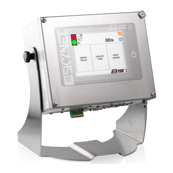
MAIN SCREEN When you power up the indicator you will see the main screen in the image below. Along the top you will see the traffic light indicator, the weight display, a folder icon, and a gear icon from left to right. The folder icon opens a diagnostic area that allows a service technician or state auditor to check the event log and other diagnostic information from the front panel. -
Page 5: Adding A Scale
Adding a Scale At the main screen press and hold the BTEK Logo, Once Red enter 2835, scroll to page 8 of 11. 1. Press Metro 2. Press Scale Configuration 3. Press Add 4. Select the Internal scale. If the scale board already contain existing data, everything will be automatically copied on the CORE processor. -
Page 6: Scale Metrological Seal
Scale Metrological Seal 1. When the scale background is red, the metrological module is sealed. To remove the seal, press the calibration button or enter a seal password to enter inside the Setup for Metrological modification and Calibration. 2. When the scale background is grey, the Instrument is not protected, so it is possible to enter inside the Setup and make Metrological modifications and Calibration. -
Page 7: Configuring Scales
Configuring Scales 1. Features (Metrological parameter of the internal scale A) – The parameters “Legal scale” & “Law” is set in the Seal Management section on page 50. 2. Specific (Analogue scale parameters, and number of digital cells) 3. Tare parameters 4. -
Page 8: Calibration Buttons
Calibration Buttons 1. Calibration data (Displays internal conversion points, and ability to change the points manually) 2. Calibration Procedures (Allow to calibrate the instrument) Note: “Zero Full Scale” is selection to perform a zero and span calibration. 3. Synchronize Restore Parameters- restores to the previous scale configuration from core board to scale card. -
Page 9: Scale Calibration
Scale Calibration Calibrating Analog Scale At the main screen press and hold the BTEK Logo, Once Red enter 2835 and tap the Metro Button on page 8 of 11. Press scale configuration, then on Scale A or B. 1. Press the calibration Button or enter software seal to access parameters. After removing metrological seal, the background will turn to gray and the shield symbol will disappear. -
Page 10: Calibrating Digital Scale
7. Confirm the calibration of the Scale (Zero – Full Scale) The instrument will automatically escape and save the calibration on the Core and Scale Board side, then confirm the calibration was saved. Calibrating Digital Scale At the main screen press and hold the BTEK Logo, Once Red enter 2835 and tap the Metro Button. - Page 11 4. Select Calibration Procedure 5. Select Eccentric Load 6. Press calibrate / “coefficienti calcolati” to starting the Eccentric procedure 7. Select the calibration Type (By side or by ID). In the example we will use the calibration by side 8. Calibration of the dead load. Check if the scale is empty and press calibrate / “coefficienti calcolati”...
- Page 12 2. Then press calibrate / “coefficienti calcolati”. 13. 10. The calibration of the 4 load cells is finished. This procedure is also used by the terminal to address the single load cells. The DD1010 ask to calculate the Coefficients of correction. Press Calculate coefficients.
-
Page 13: Diagnostics
Diagnostics The diagnostics screen can be access from the yellow folder on the top right of the weigh screen. Scale Diagnostic Log- The scale diagnostic log will display scale card and load cell errors by date and time. The diagnostic log must be turned on in the meteorological settings to record and view the events. -
Page 14: Diagnostics And Scale Event Log
Diagnostics and Scale Event Log 1. Press scale diagnostic log, then select the scale. 2. The scale statistics is displayed. 3. Press scale events, the diagnostic log is now displayed. Bil is the scale card, and C# is the individual cells that have errors. 4. -
Page 15: Replacing Digital Load Cells
Replacing Digital Load Cells Install a new, un-addressed (Defaulted) loadcell in the scale. **Prior to performing this procedure, the DD should be showing Error Code 07, or 08 meaning that it sees all the loadcells, it does not recognize one of them. If its reading Error Code 01, then you have another problem that needs corrected before you do this procedure.** 1. -
Page 16: Startup Screen (Touch Within 5 Seconds)
Normally setup and calibration is done from the application (B-TEK Button). See the start manual for other features. You will notice some of the screens say “Flynet”, B-TEK rebranded the Bilanciai version to DD1010 Skynet to addend the existing N-TEP COC. Enter password 607524, then press Login... - Page 17 Tap Utility, then Test Hardware Select Test Scale Page | 17...
- Page 18 The test scale page is below, when the card is read by the main board the dip switch settings, firmware release, and serial number will be displayed. Update Firmware- Load scale cards firmware onto a USB storeage device, then press update firmware.
-
Page 19: Test Scale
Test Scale Use this feature if you want to check the linearity of the converters without changing calibration. 1. Press 'ZERO' button when the simulator is in the 0 mV position. 2. Rotate the dial to the 2 mV position and press the 'MAX CAPACITY' button. Page | 19... -
Page 20: Test Digital Cells
Test Digital Cells Address SET- From this window all the working load cells connected to the scale board are visible. To change the address of a load cell, press the button 'SET' (set number) beside the address box. Keep in mind, if you keep track of the serial numbers position in a new scale installation, you can manually address the system to check the scale before a test truck is available. - Page 21 Reload Cells - When troubleshooting a scale, press the reload cells serial numbers. Communicating cells will be green, failed communications will turn red, as load cells are removed from the system and added, press the reload cells button. Reboot Cells- The cells and scale card can be rebooted if communication has stopped with the system.
-
Page 22: Touch Screen Calibration
Touch Screen Calibration Select the sytem tab, then display calibration. Follow the instructions on the screen by holding your finger on the target until it moves. When finished press the screen twice to exit. Page | 22... -
Page 23: Printer And Remote Display Wiring
Printer and Remote Display Wiring Cable Item# 835-300014 Page | 23... -
Page 24: Digital Scale Wiring
Digital Scale Wiring Pins with the same signal can be connected in parallel. Digital Junction Board Page | 24... -
Page 25: Analog Scale Serial Connection
Analog Scale serial connection 9-pin male connector. DESCRIPTION SIG- SIG+ EXC+ EXC- +SENSE -SENSE Serial Connections COM2 serial link / COM6&7 Skynet 9-pin female connector. PIN DESCRIPTION RX422- RX232 TX232 Page | 25... -
Page 26: Com3 Serial Link / Com 4 Skynet
RX422+ TX422- TERMINATOR TX422+ COM3 serial link / COM 4 Skynet PIN DESCRIPTION RX 232 TX 232 RTS 232 CTS 232 J2 OFF = DISCONNECTED J2 (1-2 ON) = +12V J2 (2-3 ON) = NC = Stand-by. Do not connect. RS232 connections CAUTION Maximum use conditions envisaged by standard RS232:... -
Page 27: Rs422 Connections
It is advisable to use a screened cable for connections to external devices. Remember to connect the screen to the metal part of the shell of the 9-pin connector on one end. RS422 connections If the COM2 serial port is configured with the RS422 standard, you must: •... -
Page 28: Inputs / Outputs
INPUTS / OUTPUTS Page | 28... -
Page 29: Skynet I/O Connector
Skynet I/O Connector *Pinout is the same at the DD1050 diagram above Input connection CAUTION Electrical specifications Inputs: maximum voltage < 5 Vdc maximum current < 5 mA The inputs can be controlled by clean contacts or by NPN transistors (negative common connection). -
Page 30: Configuring A Printer
Configuring a printer At the main screen press and hold the BTEK Logo, Once Red enter 2835 and tap the Printer Button on page 11 of 11. 1. Ticket Page- Configure printers, and ticket formats. 2. Printer- Configure the printer type and data port settings. VKP80III –... -
Page 31: Configuring A Scoreboard
Configuring a Scoreboard At the main screen press and hold the BTEK Logo, Once Red enter 2835 and tap the Printer Button on page 8 of 11. 7. Press Tools 8. Press Transmissions 9. Press Serial or Network 10. Press Add 11. -
Page 32: Setting Ip Address And Time And Date
Setting IP Address and Time and Date At the main screen press and hold the BTEK Logo, Once Red enter 2835 and go to page 10 of 1. Press network 2. Double click AX88772B1 3. Press specify an IP address 4. -
Page 33: Network Scale From Ddx0X0
You will need to obtain the IP Address of the primary DD and preform the following steps on the slave unit(s). KEEP IN MIND THIS WILL ONLY WORK ON THE DD1010, DD1010 Skynet, DD10150 and DD20250. 1. At the main screen press and hold the BTEK Logo, Once Red enter 2835 and tap the Metro Button 2. - Page 34 5. Enter the IP Address of the primary scale in the IP address setting 6. Leave the Port at 5001 7. Enter the Scale Name A, B, C, D or S a. If you getting weight from multiple scales IE axle weigher then you will need to add multiple Network Scales 8.
-
Page 35: Sharing Database
Sharing Database Primary DD: 1. Under the Server page Check the box [X] Enable Data Server 2. Make note of the Port Number (Default is 8095) 3. Make note of the IP Address a. If the network is DHCP then the indicator should be automatically assigned an address, however you will want to static set this address on the primary DD so that is doesn’t change. -
Page 36: Setup Slave Dd
iv. Click Ok to accept the changes and close the Network window 4. Close the Server window and tape on the Settings icon on the Database Page 5. Make a note of the Database Name field (default is STANDARD TRUCK.sdf) 6. -
Page 37: Software Update
1. Copy the file(s) from the location to the flash drive. 2. Plug in the flash drive to the DD1010 Skynet and the USB mouse 3. Move the mouse cursor down to the start button lower left-hand corner of the screen (may be hidden until you get to the button) 4. -
Page 38: Spare Parts And Useful Items
899-100225 DB9 MALE / TERMINAL STRIP CONNECTOR & SHROUD - DD SERIAL PORTS 899-100212 SINGLE SERIAL INTERFACE (1) USB TO (1) RS232 PORT DD1010 / 1050 / 2050 835-300014 RS232 PRINTER CABLE; DB9 MALE - DB25 MALE (DD & EPSON...
Need help?
Do you have a question about the DD1010 and is the answer not in the manual?
Questions and answers