
Related Manuals for SMC Networks EX510-GDN1


Summary of Contents for SMC Networks EX510-GDN1
- Page 1 Reduced wiring system DeviceNet Compatible GW unit Operation Manual EX510-GDN1 URL http://www.smcworld.com...
-
Page 2: Table Of Contents
Table of Contents Thank you for purchasing the SMC reduced wiring system EX510 series. SAFETY Please read this manual carefully before operating the digital pressure switch and make sure you understand the digital Product Summary pressure switch, its capabilities and limitations. Please keep this manual handy for future reference. -
Page 3: Safety
SAFETY This manual contains essential information for the protection of users and others from possible injury and property damage. To ensure correct handling, please follow the instructions. Do not disassemble, modify (including change of printed Please check that you fully understand the meaning of the circuit board) or repair. - Page 4 SAFETY (continue) Note The direct-current power supply should be a UL approved power supply. Execute a performance inspection after completing the 1. Limited voltage current circuit in accordance with UL508. maintenance check. A circuit which power is supplied by the secondary coil of a Please do not use if there is any error.
-
Page 5: Product Summary
Product Summary SAFETY (continue) • Do not lay wires or cables with power cable or high-voltage System structure cable in the same wiring route. • Verify the insulation of wiring. Connecting to bus Valve manifold • Take proper measurements against noise such as noise filter at upper level with SI unit when the unit is incorporated in equipment or devices. -
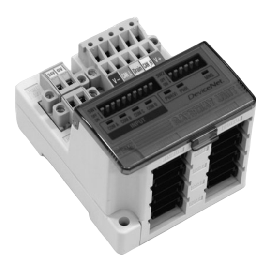
Page 6: Name Of Parts / Accessories
Name of Parts / Accessories Dimension (in mm) 25.7 Power supply Communication connector for connector (2 pcs) DeviceNet (1pc) Accessory Parts Purpose Communication Connect to DeviceNet line with an accessory socket (BUS) connector for DeviceNet ( ). * Supplying power for output instruments Power supply such as a solenoid valve with an accessory socket (PWR(V)) -
Page 7: Settings
Settings Put Claw 1 of the body under DIN rail and push it upward. Push Screw installation down Claw 2 to the opposite rail until the claw clicks securely on to rail. (Mounting procedure For removing, lever up the DIN rail fixing plate of the body with a flat blade screwdriver, and remove it by tilting Claw 2 side forward. -
Page 8: Specifications
Specifications Basic specifications Lower level bus Rated voltage 24VDC Number of branches for 4 branches for input input/ output 4 branches for output Power supply for input and controlling GW : 24VDC Range of Power supply for output:24VDC+10%/-5% Communication protocol: dedicated for SMC power supply Communication type (Warning for voltage drop is given at approx. - Page 9 Wiring (continue) Tentative fixing to the body Press fitting Branch cable wiring Fit 4 latches on the body to 4 Press the cover to the The wiring between each unit should use branch cables, and be ditches on the cover, and press body with suitable priers.
- Page 10 Wiring (continue) (3)Refer to Drawing 3 about how to connect to the unit. Communication wiring Connect DeviceNet dedicated cables to the communication connector for DeviceNet. (1)Make sure to connect the signal cables to designated pins Communication connector (Refer to Drawing 1). And tighten the connector surely to 0.5 to for DeviceNet 0.6Nm tightening torque.
- Page 11 Wiring (continue) Power supply wiring Connect power supply wiring to the two power supply 2pin B. For single power A. For dual power connectors. Power supply structure consists of 2 systems, but it supply use supply use can be used with both single power supply and dual power supply.
-
Page 12: Display/ Switch Setting
Display / Switch Setting Setting for Display Switch setting Make sure that switch setting is done with power supply turned off. Open the cover, and set DIP switch with a small flat blade screwdriver, etc. Setting of MAC ID, Baud rate, HOLD/CLR, HW/SW PWR(V) PWR COM A COM B COM C COM D... - Page 13 Display/ Switch Setting (continue) Baud rate setting (switch No. 7 to 8) Input/Output Setting (SW2) Make sure to set the baud rate in the range as follows. All of the Input/output Setting is done with SW2. settings when shipped from plant are turned OFF, set to 125kbps. Number of Input setting Number of Output setting Baud rate...
-
Page 14: Troubleshooting
Troubleshooting Overall system DeviceNet compatible communication Item Remedy / Disposal Item Remedy / Disposal • Check the power for output (24VDC) is • Check the power supply for PWR LED is UNLIT supplied. DeviceNet is supplied. • Check the branch cable is connected to SI unit.
Need help?
Do you have a question about the EX510-GDN1 and is the answer not in the manual?
Questions and answers