Table of Contents
Advertisement
Quick Links
See also:
Operating Manual
Fieldbus system
CC-Link Compatible GW unit
Operation Manual
EX510-GMJ1
URL http://www.smcworld.com
Akihabara UDX 15F, 4-14-1, Sotokanda, Chiyoda-ku, Tokyo 101-0021, JAPAN
Phone: +81 3-5207-8249 Fax: +81 3-5298-5362
Note: Specifications are subject to change without prior notice and any obligation on the part of the manufacturer.
© 2003-2017 SMC Corporation All Rights Reserved
EX※※-OMH0014-C
Advertisement
Table of Contents

Related Manuals for SMC Networks EX510-GMJ1


Summary of Contents for SMC Networks EX510-GMJ1
- Page 1 Fieldbus system CC-Link Compatible GW unit Operation Manual EX510-GMJ1 URL http://www.smcworld.com Akihabara UDX 15F, 4-14-1, Sotokanda, Chiyoda-ku, Tokyo 101-0021, JAPAN Phone: +81 3-5207-8249 Fax: +81 3-5298-5362 Note: Specifications are subject to change without prior notice and any obligation on the part of the manufacturer.
-
Page 2: Table Of Contents
Table of Contents Thank you for purchasing an SMC fieldbus system EX510 series. Safety Instructions Please read this manual carefully before operating the product and make sure you understand its capabilities and limitations. Product Summary Please keep this manual handy for future reference. Name of Parts/ Accessories Dimensions Settings... -
Page 3: Safety Instructions
Safety Instructions The product and this manual contain essential information to Do not operate in an atmosphere containing flammable or protect users and others from possible injury and property explosive gases. damage and to ensure correct handling. Fire or an explosion can result. Please check that you fully understand the definition of the This product is not designed to be explosion proof. - Page 4 Safety Instructions (continued) Note •Take sufficient shielding measures when installing at the following place. •When conformity to UL is required, the SI unit should be used (1) A place where noise due to static electricity is generated with a UL1310 Class 2 power supply. (2) A place where electric field strength is high (3) A place where there is radioactive irradiation (4) A place near power line...
-
Page 5: Product Summary
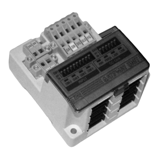
Product Summary Name of Parts/ Accessories System structure Connecting to bus at upper level Valve manifold (CC-Link) with SI unit Power supply connecting to for output 24 VDC Communication Power supply 4 sets maximum connector for connector Power supply 24 VDC GW unit CC-Link (2 pieces) -
Page 6: Dimensions
Dimensions (in mm) Settings Mounted by screw 25.7 2 × M4 Tightening torque ∗: : 0.8 Nm INPUT OUTPUT Perspective drawing INPUT OUTPUT (tolerance 0.2) COM D COM C Mounted on DIN rail COM B DIN rail COM A... -
Page 7: Specifications
Specifications Settings (continued) Basic specifications Mounting Removal 24 VDC Rated voltage DIN rail fixing plate Power supply for input and controlling GW: 24 VDC ±10% Claw 2 Power supply Power supply for output: 24 VDC+10%/-5% voltage (Warning for voltage drop is given at approx. 20 V) Power supply for input and controlling GW: Max. -
Page 8: Wiring
Wiring Internal circuit Branch wiring The wiring between each unit should use branch cables, and be (Brown) connected with branch connectors. +24 V SI unit and Input unit have 2 branch connectors for each. Pressure welding for branch connector +24 V The method of pressure welding for branch connector is explained. - Page 9 Wiring (continued) Press fitting NOTE Press the cover to the body with plier etc. 1. Select a branch cable length suitable to avoid stress Confirmation being applied to the branch connector and cable, It is completed with a check on 4 latches and provide sufficient cable length for maintenance.
- Page 10 Wiring (continued) (2) Make sure to connect a "terminating resistor" to the units at (4) Refer to Drawing 4 about how to connect to the unit. the both ends of the system (Refer to Drawing 2). Master unit Remote unit Local unit (Blue) Terminal...
-
Page 11: Display/ Switch Setting
Display/ Switch Setting Wiring (continued) Power supply wiring Setting for Display Connect power supply wiring to the two power supply 2-pin connectors. Power supply structure consists of 2 systems, but it can be used with both single power supply and separate power supply. - Page 12 Display/ Switch Setting (continued) Switch setting Swtting of transmission speed (Switch No.8 to 10) Make sure that switch setting is performed with power supply turned off. Make sure to set the transmission speed in the range as follows. Open the cover, and set DIP switch with a small flat blade All setting are turned OFF at shipment, set to 156 kbps.
-
Page 13: Troubleshooting
Troubleshooting Display/ Switch Setting (continued) Setting of the number of stations occupied Overall system (Switch No.2 to 3) Item Remedy/ Disposal The setting of the number of stations occupied is performed with •Check the power for output (24 VDC) is supplied. switch No.2 to 3. - Page 14 <MEMO> Troubleshooting (continued) CC-Link compatible communication Item Remedy/ Disposal PWR LED is •Check the power supply for input and controlling goes off GW (24 VDC) is supplied. •Check the power for output (24 VDC) is supplied. PWR(V) LED is •Check the power supply voltage for output is goes off getting as low as under 20 V.
Need help?
Do you have a question about the EX510-GMJ1 and is the answer not in the manual?
Questions and answers