Table of Contents
Advertisement
Quick Links
Advertisement
Table of Contents
Troubleshooting

Subscribe to Our Youtube Channel
Related Manuals for Supermicro SuperServer SYS-E102-9AP-LN4-E


Summary of Contents for Supermicro SuperServer SYS-E102-9AP-LN4-E
- Page 1 SuperServer ® SYS-E102-9AP-LN4-E SYS-E102-9AP-LN4-C USER’S MANUAL Revision 1.0...
- Page 2 State of California, USA. The State of California, County of Santa Clara shall be the exclusive venue for the resolution of any such disputes. Supermicro's total liability for all claims will not exceed the price paid for the hardware product.
- Page 3 If you have any questions, please contact our support team at: support@supermicro.com This manual may be periodically updated without notice. Please check the Supermicro website for possible updates to the manual revision level. Secure Data Deletion A secure data deletion tool designed to fully erase all data from storage devices can be found on our website: https://www.supermicro.com/about/policies/disclaimer.cfm?url=/wdl/utility/...
-
Page 4: Table Of Contents
Preface Preface Contents Contacting Supermicro ......................7 Chapter 1 Introduction 1.1 Overview ..........................8 1.2 System Features ........................9 Front View ...........................9 Control Panel .........................10 Rear View ..........................11 1.3 System Architecture ......................12 System Block Diagram ......................12 1.4 Motherboard Layout ......................13 Quick Reference Table ......................14 Chapter 2 Server Installation 2.1 Overview ..........................16... - Page 5 Preface 3.4 Motherboard Installation .....................23 Tools Needed ........................23 Location of Mounting Holes ....................23 Installing the Motherboard....................24 3.5 Memory Support and Installation ..................25 Memory Support ........................25 SO-DIMM Installation ......................26 SO-DIMM Removal ......................26 3.6 M.2 Installation for JMD2 and JMD4 ..................27 3.7 Motherboard Battery ......................28 Battery Removal ........................28 Proper Battery Disposal ....................28 Battery Installation ......................28...
- Page 6 6.7 Where to Get Replacement Components ................57 6.8 Reporting an Issue ......................57 Technical Support Procedures ..................57 Returning Merchandise for Service ...................57 Vendor Support Filing System ..................58 6.9 Feedback ..........................58 6.10 Contacting Supermicro ......................59 Appendix A Standardized Warning Statements for AC Systems Appendix B System Specifications...
-
Page 7: Contacting Supermicro
Super Micro Computer, Inc. 980 Rock Ave. San Jose, CA 95131 U.S.A. Tel: +1 (408) 503-8000 Fax: +1 (408) 503-8008 Email: marketing@supermicro.com (General Information) support@supermicro.com (Technical Support) Website: www.supermicro.com Europe Address: Super Micro Computer B.V. Het Sterrenbeeld 28, 5215 ML... -
Page 8: Chapter 1 Introduction
3.5" SBC 7.48 x 1.72 x 4.72 in. (190 x 44 x 120 mm) (WxDxH) Note: A Quick Reference guide can be found on the product page of the Supermicro website. Note:The following safety models associated with the SYS-E102-9AP-LN4-E/-C have been... -
Page 9: System Features
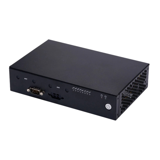
Chapter 1: Introduction 1.2 System Features The following views of the system display the main features. Refer to Appendix B for additional specifications. Front View The illustration below shows the features included on the front of the chassis. Antenna Cut-outs COM Port Control Panel Figure 1-1. -
Page 10: Control Panel
Chapter 1: Introduction Control Panel Power switches and status LEDs are located on the control panel on the front of the chassis. LAN4 LED Power LED HDD LED LAN3 LED LAN2 LED LAN1 LED LTE1 LED LTE2 LED LTE3 LED WIFI LED Power Button Figure 1-2. -
Page 11: Rear View
Chapter 1: Introduction Rear View The illustration below shows the features included on the rear of the chassis. The power supply module displays status lights. Antenna Cut-out LAN Ports Antenna Cut-out HDMI Port USB 3.0 Ports SIM Slots Power Input Kensington Lock Figure 1-3. -
Page 12: System Architecture
Chapter 1: Introduction 1.3 System Architecture System Block Diagram The block diagram below shows the connections and relationships between the subsystems and major components of the overall system. MAX. 8G SO-DIMM SUPPORTED DUAL CHANNEL Intel DDI0 Non-ECC-SODIMM0 HDMI connector DDR3L 1866 MHz DDR3L non ECC SKU FLASH FST_SPI... -
Page 13: Motherboard Layout
Chapter 1: Introduction 1.4 Motherboard Layout Below is a layout of the A2SAN-LN4-E/-C motherboard with jumper, connector and LED locations shown. See the table on the following page for descriptions. For detailed descriptions, pinout information and jumper settings, refer to Chapter 4 or the Motherboard... -
Page 14: Quick Reference Table
Chapter 1: Introduction Quick Reference Table Jumper Description Default Setting JPME2 Manufacturing Mode Pins 3-5: Normal JPME2 Power Force On Pins 2-4: Power Force On Pins 1-2 (JSIM1) JSIM_OPT1 SIM Card Detection Pins 3-4 (JSIM2) Closed: Low Active Pins 5-6 (JSIM3) Description Status Solid Green: All Power Good... - Page 15 Chapter 1: Introduction Connector Description JPH1 SATA Power Connector JPW1 8-pin 12V DC Power Connector JSIM1 Nano SIM Card Slot for JDM1 JSIM2 Nano SIM Card Slot for JDM2 JSIM3 Nano SIM Card Slot for JDM3 (bottom side layout) JSMBUS1 System Management Bus Header (bottom side layout) JUSB1 Back Panel Universal Serial Bus (USB) 3.0 Ports (USB 3.0 x 2)
-
Page 16: Chapter 2 Server Installation
Chapter 2: Server Installation Chapter 2 Server Installation 2.1 Overview This chapter provides advice and instructions for mounting your system in a server rack. If your system is not already fully integrated with processors, system memory etc., refer to Chapter 3 for details on installing those specific components. -
Page 17: Rack Precautions
Chapter 2: Server Installation • This product is not suitable for use with visual display workplace devices according to §2 of the German Ordinance for Work with Visual Display Units. Rack Precautions • Ensure that the leveling jacks on the bottom of the rack are extended to the floor so that the full weight of the rack rests on them. -
Page 18: Airflow
Chapter 2: Server Installation Airflow Equipment should be mounted into a rack so that the amount of airflow required for safe operation is not compromised. Mechanical Loading Equipment should be mounted into a rack so that a hazardous condition does not arise due to uneven mechanical loading. -
Page 19: Installing Mounting Brackets (Optional)
Chapter 2: Server Installation 2.4 Installing Mounting Brackets (Optional) The chassis includes mounting brackets that fit the VESA standard or can be wall-mounted. For wall mounting, the brackets extend out from the chassis as shown below. 1. Install the brackets using the four provided screws as shown below. Figure 2-1. -
Page 20: Chapter 3 Maintenance And Component Installation
Chapter 3: Maintenance and Component Installation Chapter 3 Maintenance and Component Installation This chapter provides instructions on installing and replacing main system components. To prevent compatibility issues, only use components that match the specifications and/or part numbers given. Installation or replacement of most components require that power first be removed from the system. -
Page 21: Accessing The System
Chapter 3: Maintenance and Component Installation 3.2 Accessing the System The CSE-E102TF chassis features a removable top cover, which allows easy access to the inside of the chassis. Removing the Top Cover 1. On the chassis rear, remove the two screws. Cover Hooks Cover Hooks Screws... -
Page 22: Static-Sensitive Devices
Chapter 3: Maintenance and Component Installation 3.3 Static-Sensitive Devices Electrostatic Discharge (ESD) can damage electronic com ponents. To avoid damaging your motherboard, it is important to handle it very carefully. The following measures are generally sufficient to protect the system PCBs from ESD. Precautions •... -
Page 23: Motherboard Installation
Chapter 3: Maintenance and Component Installation 3.4 Motherboard Installation All motherboards have standard mounting holes to fit different types of chassis. Make sure that the locations of all the mounting holes for both the motherboard and the chassis match. Although a chassis may have both plastic and metal mounting fasteners, metal ones are highly recommended because they ground the motherboard to the chassis. -
Page 24: Installing The Motherboard
Chapter 3: Maintenance and Component Installation Installing the Motherboard 1. Locate the mounting holes on the motherboard. See the previous page for the location. 2. Locate the matching mounting holes on the chassis. Align the mounting holes on the motherboard against the mounting holes on the chassis. 3. -
Page 25: Memory Support And Installation
Chapter 3: Maintenance and Component Installation 3.5 Memory Support and Installation Note: Check the Supermicro website for recommended memory modules. Important: Exercise extreme care when installing or removing DIMM modules to prevent any possible damage. Memory Support The A2SAN-LN4-E/-C supports up to 8GB DDR3L 1866MHz Non-ECC SO-DIMM in one memory slot on the bottom side of the motherboard. -
Page 26: So-Dimm Installation
Chapter 3: Maintenance and Component Installation SO-DIMM Installation 1. Insert the SO-DIMM module vertically at about a 45 degree angle. Press down until the module locks into place. The side clips will automatically secure the SO-DIMM module, locking it into place. Insert this end first Locking clip SO-DIMM Removal... -
Page 27: Installation For Jmd2 And Jmd4
Chapter 3: Maintenance and Component Installation 3.6 M.2 Installation for JMD2 and JMD4 1. Unfasten the screw from JMD2-SRW1. 2. Insert the M.2 modules into JMD2 and JMD4 and press both modules down at the same time. 3. Secure the modules by fastening the screw. JMD2-SRW1 JMD4 JMD2... -
Page 28: Motherboard Battery
Chapter 3: Maintenance and Component Installation 3.7 Motherboard Battery Battery Removal To remove the battery, follow the steps below: 1. Power off your system and unplug the power cord. 2. Remove the battery cable at the BT1 connector on the board. 3. -
Page 29: Chassis Components
Chapter 3: Maintenance and Component Installation 3.8 Chassis Components Storage Drives The CSE-E102TF chassis can accommodate a single fixed 2.5" storage drive of 7-mm thickness. It is installed to the inside of the bottom cover of the chassis. Use an enterprise quality drive. -
Page 30: System Fans
Chapter 3: Maintenance and Component Installation System Fans The chassis includes one 4-cm fan. Replacing the System Fan 1. Power down the system as described in Section 3.1 and remove the chassis cover. 2. Remove the failed fan power cable from motherboard. 3. -
Page 31: Chapter 4 Motherboard Connections
Chapter 4: Motherboard Connections Chapter 4 Motherboard Connections This section describes the connections on the A2SAN-LN4-E/-C motherboard and provides pinout definitions. Note that depending on how the system is configured, not all connections are required. The LEDs on the motherboard are also described here. A motherboard layout indicating component locations may be found in Chapter 1. -
Page 32: Headers And Connectors
Chapter 4: Motherboard Connections 4.2 Headers and Connectors Fan Headers There is one fan header with 4-pins on the motherboard. Pins 1-3 are backward compatible with traditional 3-pin fans. The onboard fan speeds are controlled by Thermal Management (via Hardware Monitoring) in the BIOS. Fan Header Pin Definitions Pin#... - Page 33 Chapter 4: Motherboard Connections Battery Connector BT1 is a two-pin connector for an external CMOS battery. This connector is also used to clear the CMOS. To clear the CMOS, remove the battery, short pins 1-2 for more than 10 seconds and then install the battery.
- Page 34 Chapter 4: Motherboard Connections M.2 Slot Pin Definition for JMD1 M.2 Pin Definition (JMD1) Pin# Definition Pin# Definition P3V3SB P3V3SB FULL_CARD_POWER_OFF#(PU to P1V8SB only) USB_D- W_DISABLE1#(PU to P3V3SB only) USB_D+ LED (ACTIVE LOW) KEY B KEY B KEY B KEY B KEY B KEY B KEY B...
- Page 35 Chapter 4: Motherboard Connections M.2 Slot Pin Definition for JMD2 M.2 Pin Definition (JMD2) Pin# Definition Pin# Definition P3V3SB P3V3SB FULL_CARD_POWER_OFF#(PU to P1V8SB only) USB_D- W_DISABLE1#(PU to P3V3SB only) USB_D+ LED (ACTIVE LOW) KEY B KEY B KEY B KEY B KEY B KEY B KEY B...
- Page 36 Chapter 4: Motherboard Connections M.2 Slot Pin Definition for JMD3 M.2 Pin Definition (JMD3) Pin# Definition Pin# Definition P3V3SB P3V3SB FULL_CARD_POWER_OFF#(PU to P1V8SB only) USB_D- W_DISABLE1#(PU to P3V3SB only) USB_D+ LED (ACTIVE LOW) KEY B KEY B KEY B KEY B KEY B KEY B KEY B...
- Page 37 Chapter 4: Motherboard Connections M.2 Slot Pin Definition for JMD4 M.2 Pin Definition (JMD4) Pin# Definition Pin# Definition P3V3SB USB_D+ P3V3SB USB_D- NGFF_WIFI_LED (ACTIVE LOW) NGFF_CONN_UART_WAKE_N (PU to P3V3SB only) KEY E KEY E KEY E KEY E KEY E KEY E KEY E KEY E...
-
Page 38: Control Panel
JF1 contains header pins for various buttons and indicators that are normally located on a control panel at the front of the chassis. These connectors are designed specifically for use with Supermicro chassis. See the figure below for the descriptions of the front control panel buttons and LED indicators. - Page 39 Chapter 4: Motherboard Connections HDD LED The HDD LED connection is located on pins 5 and 6 of JF1. Attach a cable here to indicate the status of HDD-related activities, including SATA activities. Refer to the table below for pin definitions. HDD LED Pin Definitions (JF1) Pin#...
-
Page 40: Input/Output Ports
Chapter 4: Motherboard Connections 4.3 Input/Output Ports Rear I/O Ports Definition Description LAN1 SIM Slot 1 (JMD1) LAN2 SIM Slot 2 (JMD2) LAN3 SIM Slot 3 (JMD3) LAN4 USB1 HDMI Port USB0 HDMI Port The HDMI (High-Definition Multimedia Interface) port is used to display both high definition video and digital sound through an HDMI-capable display, using an HDMI cable. - Page 41 Chapter 4: Motherboard Connections Nano SIM Slots Thre are two Nano SIM card slots on the I/O back panel. Nano SIM slot 1 is for JMD1 and Nano SIM slot 2 is for JDM2. Nano SIM slot 3 (JMD3) on the bottom of the motherboard LAN Ports Four Gigabit Ethernet ports (LAN1 - LAN4) are located on the I/O back panel.
-
Page 42: Jumpers
Chapter 4: Motherboard Connections 4.4 Jumpers How Jumpers Work To modify the operation of the motherboard, jumpers can be used to choose between optional settings. Jumpers create shorts between two pins to change the function of the connector. Pin 1 is identified with a square solder pad on the printed circuit board. See the diagram below for an example of jumping pins 1 and 2. -
Page 43: Led Indicators
Chapter 4: Motherboard Connections 4.5 LED Indicators LAN LEDs Four LAN ports (LAN 1 and LAN 2) are located on the I/O back panel of the motherboard. Each LAN port has two LEDs. The green LED indicates activity, while the other Link LED may be green, amber, or off to indicate the speed of the connection. -
Page 44: Chapter 5 Software
USB/SATA DVD drive, or a USB flash drive, or the IPMI KVM console. 2. Retrieve the proper RST/RSTe driver. Go to the Supermicro web page for your motherboard and click on "Download the Latest Drivers and Utilities", select the proper driver, and copy it to a USB flash drive. - Page 45 Chapter 5: Software 4. During Windows Setup, continue to the dialog where you select the drives on which to install Windows. If the disk you want to use is not listed, click on “Load driver” link at the bottom left corner. Figure 5-2.
-
Page 46: Driver Installation
After creating a CD/DVD with the ISO files, insert the disk into the CD/DVD drive on your system and the display shown in Figure B-1 should appear. Another option is to go to the Supermicro website at http://www.supermicro.com. Find the product page for your motherboard, and "Download the Latest Drivers and Utilities". -
Page 47: Superdoctor ® 5
5.3 SuperDoctor ® The Supermicro SuperDoctor 5 is a program that functions in a command-line or web-based interface for Windows and Linux operating systems. The program monitors such system health information as CPU temperature, system voltages, system power consumption, fan speed, and provides alerts via email or Simple Network Management Protocol (SNMP). -
Page 48: Ipmi
BIOS settings that are related to IPMI. For general documentation and information on IPMI, visit our website at: http://www.supermicro.com/products/nfo/IPMI.cfm. BMC ADMIN User Password For security, each system is assigned a unique default BMC password for the ADMIN user. -
Page 49: Chapter 6 Troubleshooting And Support
Chapter 6: Troubleshooting and Support Chapter 6 Troubleshooting and Support 6.1 Information Resources Website A great deal of information is available on the Supermicro website. Products Figure 7-1. Supermicro Website • Specifications for servers and other hardware are available by clicking the Products. -
Page 50: Intelligent Platform Management Interface (Ipmi)
Security Center for recent security notices Supermicro Phone and Addresses 6.2 Intelligent Platform Management Interface (IPMI) The system supports the Intelligent Platform Management Interface (IPMI). IPMI is used to provide remote access, monitoring and management. There are several BIOS settings that are related to IPMI. -
Page 51: Troubleshooting Procedures
Chapter 6: Troubleshooting and Support 6.3 Troubleshooting Procedures Use the following procedures to troubleshoot your system. If you have followed all of the procedures below and still need assistance, refer to the Technical Support Procedures Returning Merchandise for Service section(s) in this chapter. Power down the system before changing any non hot-swap hardware components. -
Page 52: No Video
Chapter 6: Troubleshooting and Support No Video 1. If the power is on but you have no video, remove all the add-on cards and cables. 2. As you try to power up the system, note any beep codes. Refer to the next section for details on beep codes. - Page 53 Chapter 6: Troubleshooting and Support Note: Refer to the product page on our website at http://www.supermicro.com for memory and CPU support and updates. 3. HDD support: Make sure that all hard disk drives (HDDs) work properly. Replace the bad HDDs with good ones.
-
Page 54: Bios Error Beep (Post) Codes
When BIOS performs the Power On Self Test, it writes checkpoint codes to I/O port 0080h. If the computer cannot complete the boot process, a diagnostic card can be attached to the computer to read I/O port 0080h (Supermicro p/n AOC-LPC80-20). For information on AMI updates, please refer to http://www.ami.com/products/. -
Page 55: Crash Dump Using Ipmi
Users can view, export records provide information to support staff. You can download a crash dump of status information using IPMI. The IPMI manual is available at https://www.supermicro.com/solutions/IPMI.cfm. Check IPMI Error Log Note: By default, all event types will be selected so that user can view all events. -
Page 56: Cmos Clear
Chapter 6: Troubleshooting and Support 6.6 CMOS Clear JBT1 is used to clear CMOS, which will also clear any passwords. Instead of pins, this jumper consists of contact pads to prevent accidentally clearing the contents of CMOS. To Clear CMOS 1. -
Page 57: Where To Get Replacement Components
6.7 Where to Get Replacement Components If you need replacement parts for your system, to ensure the highest level of professional service and technical support, purchase exclusively from our Supermicro Authorized Distributors/System Integrators/Resellers. A list can be found at: http://www.supermicro.com. -
Page 58: Vendor Support Filing System
For issues related to Red Hat Enterprise Linux, since it is a subscription based OS, contact your account representative. 6.9 Feedback Supermicro values your feedback as we strive to improve our customer experience in all facets of our business. Please email us at techwriterteam@supermicro.com to provide feedback on our manuals. -
Page 59: Contacting Supermicro
Chapter 6: Troubleshooting and Support 6.10 Contacting Supermicro Headquarters Address: Super Micro Computer, Inc. 980 Rock Ave. San Jose, CA 95131 U.S.A. Tel: +1 (408) 503-8000 Fax: +1 (408) 503-8008 Email: marketing@supermicro.com (General Information) support@supermicro.com (Technical Support) Website: www.supermicro.com Europe Address: Super Micro Computer B.V. -
Page 60: Appendix A Standardized Warning Statements For Ac Systems
Supermicro's Technical Support department for assistance. Only certified technicians should attempt to install or configure components. Read this appendix in its entirety before installing or configuring components in the Supermicro chassis. These warnings may also be found on our website at http://www.supermicro.com/about/... - Page 61 Appendix A: Warning Statements Warnung WICHTIGE SICHERHEITSHINWEISE Dieses Warnsymbol bedeutet Gefahr. Sie befinden sich in einer Situation, die zu Verletzungen führen kann. Machen Sie sich vor der Arbeit mit Geräten mit den Gefahren elektrischer Schaltungen und den üblichen Verfahren zur Vorbeugung vor Unfällen vertraut. Suchen Sie mit der am Ende jeder Warnung angegebenen Anweisungsnummer nach der jeweiligen Übersetzung in den übersetzten Sicherheitshinweisen, die zusammen mit diesem Gerät ausgeliefert wurden.
- Page 62 Appendix A: Warning Statements . ٌ ا ك ً ف حالة و ٌ يك أى تتسبب ف اصابة جسذ ة ٌ هذا الزهز ع ٌ خطز !تحذ ز قبل أى تعول عىل أي هعذات،يك عىل علن بالوخاطز ال ا ٌجوة عي الذوائز ٍ...
- Page 63 Appendix A: Warning Statements Warnung Vor dem Anschließen des Systems an die Stromquelle die Installationsanweisungen lesen. ¡Advertencia! Lea las instrucciones de instalación antes de conectar el sistema a la red de alimentación. Attention Avant de brancher le système sur la source d'alimentation, consulter les directives d'installation. .יש...
- Page 64 Appendix A: Warning Statements Warnung Dieses Produkt ist darauf angewiesen, dass im Gebäude ein Kurzschluss- bzw. Überstromschutz installiert ist. Stellen Sie sicher, dass der Nennwert der Schutzvorrichtung nicht mehr als: 250 V, 20 A beträgt. ¡Advertencia! Este equipo utiliza el sistema de protección contra cortocircuitos (o sobrecorrientes) del edificio.
- Page 65 Appendix A: Warning Statements Power Disconnection Warning Warning! The system must be disconnected from all sources of power and the power cord removed from the power supply module(s) before accessing the chassis interior to install or remove system components. 電源切断の警告 システムコンポーネントの取り付けまたは取り外しのために、...
- Page 66 Appendix A: Warning Statements אזהרה מפני ניתוק חשמלי !אזהרה יש לנתק את המערכת מכל מקורות החשמל ויש להסיר את כבל החשמלי מהספק .לפני גישה לחלק הפנימי של המארז לצורך התקנת או הסרת רכיבים يجب فصم اننظاو من جميع مصادر انطاقت وإ ز انت سهك انكهرباء من وحدة امداد انطاقت...
- Page 67 Appendix A: Warning Statements Attention Il est vivement recommandé de confier l'installation, le remplacement et la maintenance de ces équipements à des personnels qualifiés et expérimentés. !אזהרה .צוות מוסמך בלבד רשאי להתקין, להחליף את הציוד או לתת שירות עבור הציוד واملدربيه...
- Page 68 Appendix A: Warning Statements Warnung Diese Einheit ist zur Installation in Bereichen mit beschränktem Zutritt vorgesehen. Der Zutritt zu derartigen Bereichen ist nur mit einem Spezialwerkzeug, Schloss und Schlüssel oder einer sonstigen Sicherheitsvorkehrung möglich. ¡Advertencia! Esta unidad ha sido diseñada para instalación en áreas de acceso restringido. Sólo puede obtenerse acceso a una de estas áreas mediante la utilización de una herramienta especial, cerradura con llave u otro medio de seguridad.
- Page 69 Appendix A: Warning Statements Battery Handling Warning! There is the danger of explosion if the battery is replaced incorrectly. Replace the battery only with the same or equivalent type recommended by the manufacturer. Dispose of used batteries according to the manufacturer's instructions 電池の取り扱い...
- Page 70 Appendix A: Warning Statements هناك خطر من انفجار يف حالة اسحبذال البطارية بطريقة غري صحيحة فعليل اسحبذال البطارية فقط بنفس النىع أو ما يعادلها مام أوصث به الرشمة املصنعة جخلص من البطاريات املسحعملة وفقا لحعليامت الرشمة الصانعة 경고! 배터리가 올바르게 교체되지 않으면 폭발의 위험이 있습니다. 기존 배터리와 동일하거나 제 조사에서...
- Page 71 Appendix A: Warning Statements ¡Advertencia! Puede que esta unidad tenga más de una conexión para fuentes de alimentación. Para cortar por completo el suministro de energía, deben desconectarse todas las conexiones. Attention Cette unité peut avoir plus d'une connexion d'alimentation. Pour supprimer toute tension et tout courant électrique de l'unité, toutes les connexions d'alimentation doivent être débranchées.
- Page 72 Appendix A: Warning Statements Backplane Voltage Warning! Hazardous voltage or energy is present on the backplane when the system is operating. Use caution when servicing. バックプレーンの電圧 システムの稼働中は危険な電圧または電力が、 バックプレーン上にかかっています。 修理する際には注意く ださい。 警告 当系统正在进行时,背板上有很危险的电压或能量,进行维修时务必小心。 警告 當系統正在進行時,背板上有危險的電壓或能量,進行維修時務必小心。 Warnung Wenn das System in Betrieb ist, treten auf der Rückwandplatine gefährliche Spannungen oder Energien auf.
- Page 73 Appendix A: Warning Statements هناك خطز مه التيار الكهزبايئ أوالطاقة املىجىدة عىل اللىحة عندما يكىن النظام يعمل كه حذ ر ا عند خدمة هذا الجهاس 경고! 시스템이 동작 중일 때 후면판 (Backplane)에는 위험한 전압이나 에너지가 발생 합니다. 서비스 작업 시 주의하십시오. Waarschuwing Een gevaarlijke spanning of energie is aanwezig op de backplane wanneer het systeem in gebruik is.
- Page 74 Appendix A: Warning Statements תיאום חוקי החשמל הארצי !אזהרה .התקנת הציוד חייבת להיות תואמת לחוקי החשמל המקומיים והארציים تركيب املعدات الكهربائية يجب أن ميتثل للقىاويه املحلية والىطىية املتعلقة بالكهرباء 경고! 현 지역 및 국가의 전기 규정에 따라 장비를 설치해야 합니다. Waarschuwing Bij installatie van de apparatuur moet worden voldaan aan de lokale en nationale elektriciteitsvoorschriften.
- Page 75 Appendix A: Warning Statements Attention La mise au rebut ou le recyclage de ce produit sont généralement soumis à des lois et/ou directives de respect de l'environnement. Renseignez-vous auprès de l'organisme compétent. סילוק המוצר !אזהרה .סילוק סופי של מוצר זה חייב להיות בהתאם להנחיות וחוקי המדינה التخلص...
- Page 76 Appendix A: Warning Statements Warnung Gefährlich Bewegende Teile. Von den bewegenden Lüfterblätter fern halten. Die Lüfter drehen sich u. U. noch, wenn die Lüfterbaugruppe aus dem Chassis genommen wird. Halten Sie Finger, Schraubendreher und andere Gegenstände von den Öffnungen des Lüftergehäuses entfernt.
- Page 77 Verbindungskabeln, Stromkabeln und/oder Adapater, die Ihre örtlichen Sicherheitsstandards einhalten. Der Gebrauch von anderen Kabeln und Adapter können Fehlfunktionen oder Feuer verursachen. Die Richtlinien untersagen das Nutzen von UL oder CAS zertifizierten Kabeln (mit UL/CSA gekennzeichnet), an Geräten oder Produkten die nicht mit Supermicro gekennzeichnet sind.
- Page 78 .قيرح وأ لطع يف ببستي دق ىرخأ تالوحمو تالباك يأ مادختسا .ميلسلا سباقلاو لصوملا مجح لبق نم ةدمتعملا تالباكلا مادختسا تادعملاو ةيئابرهكلا ةزهجألل ةمالسلا نوناق رظحيUL وأCSA ( ةمالع لمحت يتلاوUL/CSA) لبق نم ةددحملاو ةينعملا تاجتنملا ريغ ىرخأ تادعم يأ عمSupermicro.
- Page 79 사항을 준수하여 제공되거나 지정된 연결 혹은 구매 케이블, 전원 케이블 및 AC 어댑터를 사용하십시오. 다른 케이블이나 어댑터를 사용하면 오작동이나 화재가 발생할 수 있습니다. 전기 용품 안전법은 UL 또는 CSA 인증 케이블 (코드에 UL / CSA가 표시된 케이블)을 Supermicro 가 지정한 제품 이외의 전기 장치에 사용하는 것을 금지합니다. Stroomkabel en AC-Adapter...
-
Page 80: Appendix B System Specifications
Appendix B: System Specifications Appendix B System Specifications Processor A2SAN-LN4-E: Intel® Atom™ x5-E3940 Processor, Quad Core, 2M Cache, 1.6GHz-1.8GHz, TDP 9.5W A2SAN-LN4-C: Intel® Celeron® J3455 Processor, Quad Core, 2M Cache, 1.5GHz-2.3GHz, TDP 10W Note: Refer to the motherboard specifications pages on our website for updates to supported processors. Chipset System on Chip (SoC) BIOS... - Page 81 Appendix B: System Specifications Regulatory Compliance FCC, ICES, CE, UKCA, VCCI, RCM, NRTL, CB Applied Directives, Standards EMC/EMI: 2014/30/EU (EMC Directive) Electromagnetic Compatibility Regulations 2016 FCC Part 15 Subpart B ICES-003 VCCI-CISPR 32 AS/NZS CISPR 32 BS/EN55032 BS/EN55035 CISPR 32 CISPR 35 BS/EN 61000-3-2 BS/EN 61000-3-3...
Need help?
Do you have a question about the SuperServer SYS-E102-9AP-LN4-E and is the answer not in the manual?
Questions and answers