Table of Contents
Advertisement
Quick Links
Advertisement
Table of Contents

Related Manuals for Supermicro SuperO A1SAM-2750F


Summary of Contents for Supermicro SuperO A1SAM-2750F
- Page 1 A1SAM-2750F A1SAM-2550F A1SRM-2758F A1SRM-2558F USER’S MANUAL Revision 1.0...
- Page 2 This product, including software and docu- mentation, is the property of Supermicro and/or its licensors, and is supplied only under a license. Any use or reproduction of this product is not allowed, except as expressly permitted by the terms of said license.
-
Page 3: About This Motherboard
Please refer to our website at (http://www.supermicro.com/products/) for processor and memory support updates. This product is intended to be installed and serviced by professional technicians. -
Page 4: Conventions Used In The Manual
A1SAM/A1SRM Series Motherboard User’s Manual Conventions Used in the Manual Special attention should be given to the following symbols for proper installation and to prevent damage done to the components or injury to yourself: Warning: Critical information to prevent damage to the components or injury to your- self. -
Page 5: Contacting Supermicro
Super Micro Computer, Inc. 980 Rock Ave. San Jose, CA 95131 U.S.A. Tel: +1 (408) 503-8000 Fax: +1 (408) 503-8008 Email: marketing@supermicro.com (General Information) support@supermicro.com (Technical Support) Web Site: www.supermicro.com Europe Address: Super Micro Computer B.V. Het Sterrenbeeld 28, 5215 ML... -
Page 6: Table Of Contents
A1SAM/A1SRM Series Motherboard User’s Manual Table of Contents Preface Chapter 1 Introduction Overview ......................1-1 Processor Overview ..................1-10 Special Features ....................1-11 PC Health Monitoring ..................1-11 ACPI Features ....................1-11 Power Supply ....................1-12 Chapter 2 Installation Standardized Warning Statements ..............2-1 Static-Sensitive Devices .................. - Page 7 Table of Contents Overheat LED Header ................2-22 TPM Header/Port 80 Header ..............2-23 LAN3/LAN4 LED Indication Header ............2-23 Power SMB (I C) Connector ..............2-24 System Management Bus Header ............2-24 Standby Power ..................2-25 Jumper Settings .................... 2-26 Explanation of Jumpers ................
- Page 8 A1SAM/A1SRM Series Motherboard User’s Manual Appendix A BIOS Error Beep Codes BIOS Error Beep Codes .................A-1 Appendix B Software Installation Instructions Installing Software Programs ................B-1 Installing SuperDoctor5 ...................B-2 Appendix C UEFI BIOS Recovery Instructions An Overview to the UEFI BIOS ..............C-1 How to Recover the UEFI BIOS Image (-the Main BIOS Block)....C-1 To Recover the Main BIOS Block Using a USB-Attached Device....C-1 viii...
-
Page 9: Chapter 1 Introduction
Checklist Congratulations on purchasing your computer motherboard from an acknowledged leader in the industry. Supermicro boards are designed with the utmost attention to detail to provide you with the highest standards in quality and performance. Please check that the following items have all been included with your motherboard. - Page 10 A1SAM/A1SRM Series Motherboard User’s Manual A1SAM-2750F Motherboard Image (Rev. 1.01) Note: All graphics shown in this manual were based upon the latest PCB Revision available at the time of publishing of the manual. The motherboard you've received may or may not look exactly the same as the graphics shown in this manual.
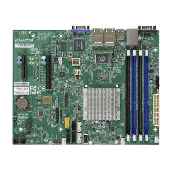
- Page 11 Chapter 1: Introduction A1SAM-2550F/A1SRM-2558F Motherboard Image (Rev. 1.01) Note: All graphics shown in this manual were based upon the latest PCB Revision available at the time of publishing of the manual. The motherboard you've received may or may not look exactly the same as the graphics shown in this manual.
- Page 12 A1SAM/A1SRM Series Motherboard User’s Manual A1SAM/A1SRM Series Motherboard Layout (Rev. 1.01) LAN2/LAN4 USB0/1 LAN1/LAN3 USB 2/3 JUIDB1 COM1 JVGA1 IPMI_LAN JLAN2 JLAN1 LAN3/4 LED A1SAM/A1SRM Series Rev. 1.01 PWRI2C BIOS JBAT1 SoC Processor JBT1 BATTERY BUZZER COM2 USB4/5 Important Notes to the User 1.
-
Page 13: Connector Description
Chapter 1: Introduction A1SAM/A1SRM Series Motherboard Quick Reference A1SAM/A1SRM Series Motherboard Jumpers Jumper Description Default JBT1 CMOS Clear Off (Normal) Onboard Buzzer (Also see the Connectors section below) Pins 6-7 (Enabled) C1/JI SMB to PCI-Exp. Slots Pins 2-3 (Disabled) JPG1 VGA Enable Pins 1-2 (Enabled) JPL1... - Page 14 A1SAM/A1SRM Series Motherboard User’s Manual Backpanel VGA Port A1SAM/A1SRM Series Motherboard LED Indicators Description Color/State Status LED2 BMC/IPMI Heartbeat LED Green: Blinking BMC/IPMI: Normal LED3 Power LED Green: On System Power On LED7 UID Switch LED Blue: On Unit Identified Solid On: Overheat, LED8 Overheat/PWR Fail/Fan Fail LED...
-
Page 15: Motherboard Features
Chapter 1: Introduction Motherboard Features Single Intel® C2000 Tri-Gate 22nm SoC (System-on-a Chip) Series processor in an FCBGA 1283 package Each SoC supports 4 cores or 8 cores Refer to the table below for SoC support on MB model: Memory Four (4) memory slots support up to 64 GB of DDR3 Unbuf- fered (UDIMM) ECC or Non-ECC 1600/1333 MHz (1.5V, 1.35V) memory... -
Page 16: Power Configuration
System resource alert via SuperDoctor ® SuperDoctor® 5, Watch Dog, NMI Chassis Intrusion header and detection CD Utilities Download from www.supermicro.com Other ROHS (Full Compliance, Lead Free) Dimensions uATX form factor (9.6" x 7.5") (243.84 mm x 190.50 mm) Model Variation Table... -
Page 17: System Block Diagram
Chapter 1: Introduction A1SAM/A1SRM Series Motherboard Block Diagram FLASH 128Mb AVOTON SOC PCIE x 8 JPCIE1 PCIE 2.0 x 8 SLOT PEG [8..15] JPCIE2 PCIE 2.0 x 4 SLOT (Optional) PCIE x 4 JPCIE3 PEG [4..7] PCIE 2.0 x 4 SLOT USB Hub USB 2.0 USB 2.0... -
Page 18: Processor Overview
A1SAM/A1SRM Series Motherboard User’s Manual Processor Overview The A1SAM/A1SRM Series motherboard supports a 2nd-generation 64-bit, Intel® Atom™ C2000 Tri-Gate SoC (System-on-a- Chip) Series processor based on low- power 22nm Silvermont microarchitecture in an FCBGA 1283 package. Built upon the functionality and capability of the C2000 SoC Series processor, the A1SAM/ A1SRM Series motherboard provides unprecedented enhancements to network routing, internet security, system performance, and power efficiency. -
Page 19: Special Features
Chapter 1: Introduction Special Features Recovery from AC Power Loss Basic I/O System (BIOS) provides a setting for you to determine how the system will respond when AC power is lost and then restored to the system. You can choose for the system to remain powered off, (in which case you must press the power switch to turn it back on), or for it to automatically return to a power-on state. -
Page 20: Power Supply
A1SAM/A1SRM Series Motherboard User’s Manual way to integrate power management features throughout a PC system, including its hardware, operating system and application software. This enables the system to automatically turn on and off peripherals such as CD-ROMs, network cards, hard disk drives and printers. -
Page 21: Chapter 2 Installation
The following statements are industry-standard warnings, provided to warn the user of situations which have the potential for bodily injury. Should you have questions or experience difficulty, contact Supermicro's Technical Support department for assis- tance. Only certified technicians should attempt to install or configure components. - Page 22 A1SAM/A1SRM Series Motherboard User’s Manual Attention Danger d'explosion si la pile n'est pas remplacée correctement. Ne la remplacer que par une pile de type semblable ou équivalent, recommandée par le fabricant. Jeter les piles usagées conformément aux instructions du fabricant. ¡Advertencia! Existe peligro de explosión si la batería se reemplaza de manera incorrecta.
-
Page 23: Product Disposal
Chapter 2: Installation Product Disposal Warning! Ultimate disposal of this product should be handled according to all national laws and regulations. 製品の廃棄 この製品を廃棄処分する場合、 国の関係する全ての法律 ・ 条例に従い処理する必要が あり ます。 警告 本产品的废弃处理应根据所有国家的法律和规章进行。 警告 本產品的廢棄處理應根據所有國家的法律和規章進行。 Warnung Die Entsorgung dieses Produkts sollte gemäß allen Bestimmungen und Gesetzen des Landes erfolgen. -
Page 24: Static-Sensitive Devices
A1SAM/A1SRM Series Motherboard User’s Manual القىانين واللىائح الىطنية جميع وفقا ل ينبغي التعامل معه هذا المنتج من التخلص النهائي عند 경고! 이 제품은 해당 국가의 관련 법규 및 규정에 따라 폐기되어야 합니다. Waarschuwing De uiteindelijke verwijdering van dit product dient te geschieden in overeenstemming met alle nationale wetten en reglementen. -
Page 25: Memory Support
DIMM modules with a pair of memory modules of the same type and same size will result in better memory performance. Note 1: Check the Supermicro website for recommended memory mod- ules. Note 2: Be sure to use memory modules of the same type, same speed, and same frequency on the same motherboard. -
Page 26: Populating Memory Modules
A1SAM/A1SRM Series Motherboard User’s Manual Populating Memory Modules 1. Install the desired number of DIMMs into the memory slots, starting with DIM- MA1, then DIMMB1, then DIMMA2, then DIMMB2. Pay attention to the notch along the bottom of the module to prevent incorrect DIMM module installation. 2. - Page 27 Chapter 2: Installation Note: Due to memory allocation to system devices, the amount of memory that remains available for operational use will be reduced when 4 GB of RAM is used. The reduction in memory availability is dispropor- tional. See the following table for details. Possible System Memory Allocation &...
-
Page 28: Motherboard Installation
A1SAM/A1SRM Series Motherboard User’s Manual Motherboard Installation All motherboards have standard mounting holes to fit different types of chassis. Make sure that the locations of all the mounting holes for both motherboard and chassis match. Although a chassis may have both plastic and metal mounting fas- teners, metal ones are highly recommended because they ground the motherboard to the chassis. -
Page 29: Installing The Motherboard
Chapter 2: Installation Installing the Motherboard 1. Install the I/O shield into the back of the chassis. 2. Locate the mounting holes on the motherboard. (See the previous page.) 3. Locate the matching mounting holes on the chassis. Align the mounting holes on the motherboard against the mounting holes on the chassis. -
Page 30: Connectors/Io Ports
A1SAM/A1SRM Series Motherboard User’s Manual Connectors/IO Ports The I/O ports are color coded in conformance with the Industry Standards. See the figure below for the colors and locations of the various I/O ports. Backplane I/O Panel A1SAM/A1SRM Series Rev. 1.01 Backplane I/O Panel A. -
Page 31: Universal Serial Bus (Usb)
Chapter 2: Installation Universal Serial Bus (USB) Four Universal Serial Bus 2.0 ports (0/1, 2/3) are located on the I/O back panel. In addition, a USB header that supports two USB 2.0 connectors (USB 4/5) and a Type A USB 2.0 port (USB 6) are also located on the motherboard to provide front accessible USB support. -
Page 32: Ethernet Ports
A1SAM/A1SRM Series Motherboard User’s Manual Ethernet Ports LAN Ports Pin Definition Four Gigabit Ethernet ports (LAN1/3, Pin# Definition LAN2/4) are located next to the VGA P2V5SB SGND Connector on the I/O Backpanel TD0+ Act LED to provide network connections. In TD0- P3V3SB addition, an IPMI_Dedicated LAN,... -
Page 33: Unit Identifier Switch
Note: UID can also be triggered via IPMI on the motherboard. For more information on IPMI, please refer to the IPMI User's Guide posted on our Website @http://www.supermicro.com. A. UID Switch B. Rear UID LED (on the moth- erboard) C. Front UID LED... -
Page 34: Front Control Panel
These connectors are designed spe- cifically for use with Supermicro chassis. See the figure below for the descriptions of the front control panel buttons and LED indicators. Refer to the following section for descriptions and pin definitions. -
Page 35: Front Control Panel Pin Definitions
Chapter 2: Installation Front Control Panel Pin Definitions NMI Button NMI Button Pin Definitions (JF1) The non-maskable interrupt button header is located on pins 19 and 20 Pin# Definition of JF1. Refer to the table on the right Control for pin definitions. Ground Power LED Power LED... -
Page 36: Hdd Led
A1SAM/A1SRM Series Motherboard User’s Manual HDD LED HDD LED Pin Definitions (JF1) The HDD LED connection is located Pin# Definition on pins 13 and 14 of JF1. Attach a 3.3V Standby cable here to indicate the status of HD LED HDD-related activities, including IDE, SATA activities. -
Page 37: Overheat (Oh)/Fan Fail/Pwr Fail/Uid Led
Chapter 2: Installation Overheat (OH)/Fan Fail/PWR Fail/ OH/Fan Fail/ PWR Fail/Blue_UID UID LED LED Pin Definitions (JF1) Pin# Definition Connect an LED cable to pins 7 and Blue_UID LED 8 of Front Control Panel to use the OH/Fan Fail/Power Fail Cathode Overheat/Fan Fail/Power Fail and UID LED connections. -
Page 38: Reset Button
A1SAM/A1SRM Series Motherboard User’s Manual Reset Button Reset Button Pin Definitions (JF1) The Reset Button connection is lo- Pin# Definition cated on pins 3 and 4 of JF1. Attach Reset it to a hardware reset switch on the Ground computer case to reset the system. Refer to the table on the right for pin definitions. -
Page 39: Connecting Cables
Chapter 2: Installation Connecting Cables This section provides brief descriptions and pin-out definitions for onboard headers and connectors. Be sure to use the correct cable for each header or connector. For information on Backpanel USB and Front Panel USB ports, refer to Page 2-13. ATX Power 24-pin Connector ATX Power Connector Pin Definitions (JPW1) -
Page 40: Fan Headers (Fan 1 ~ Fan 3)
A1SAM/A1SRM Series Motherboard User’s Manual Fan Headers (Fan 1 ~ Fan 3) Fan Header Pin Definitions This motherboard has three fan headers (Fan Pin# Definition 1~Fan 3). These fans are 4-pin fan headers. Al- Ground (Black) though pins 1-3 of the fan headers are backward 2.5A/+12V compatible with the traditional 3-pin fans, we (Red) -
Page 41: Internal Buzzer (Sp1)
Chapter 2: Installation Internal Buzzer (SP1) Internal Buzzer Pin Definition The Internal Buzzer (SP1) can be Pin# Definitions used to provide audible indications for Pin 1 Pos. (+) Beep In various beep codes. See the table on Pin 2 Neg. (-) Alarm the right for pin definitions. -
Page 42: Dom Pwr Connector (Jsd1)
A1SAM/A1SRM Series Motherboard User’s Manual DOM PWR Connector (JSD1) DOM PWR Pin Definitions The Disk-On-Module (DOM) power Pin# Definition connector, located at JSD1, provides 5V power to a solid state DOM storage Ground device connected to one of the SATA Ground ports. -
Page 43: Tpm Header/Port 80 Header
Chapter 2: Installation TPM Header/Port 80 Header TPM/Port 80 Header Pin Definitions A Trusted Platform Module/Port 80 Pin # Definition Pin # Definition header, located at JTPM1, provides LCLK STPM support and Port 80 connec- LFRAME# <(KEY)> tion. Use this header to enhance LRESET# +5V (X) LAD 3... -
Page 44: Power Smb
A1SAM/A1SRM Series Motherboard User’s Manual Power SMB (I C) Connector PWR SMB Pin Definitions Power System Management Bus (I Pin# Definition Connector (JPI C1) monitors power Clock supply, fan and system temperatures. Data See the table on the right for pin PWR Fail definitions. -
Page 45: Standby Power
Chapter 2: Installation Standby Power Standby Power Pin Definitions The 5V Standby Power header is located at Pin# Definition JSTBY1 on the motherboard. See the layout +5V Standby below for the location. Ground Wake-up LAN2/LAN4 USB0/1 LAN1/LAN3 USB 2/3 A. 5V Standby PWR JUIDB1 COM1 JVGA1... -
Page 46: Jumper Settings
A1SAM/A1SRM Series Motherboard User’s Manual Jumper Settings Explanation of Jumpers To modify the operation of the mother- board, jumpers can be used to choose between optional settings. Jumpers create shorts between two pins to change the function of the connector. Pin 1 is identified with a square solder pad on the printed circuit board. -
Page 47: Cmos Clear
Chapter 2: Installation CMOS Clear JBT1 is used to clear CMOS. Instead of pins, this "jumper" consists of contact pads to prevent accidental clearing of CMOS. To clear CMOS, use a metal object such as a small screwdriver to touch both pads at the same time to short the connec- tion. -
Page 48: Watch Dog Timer Enable
A1SAM/A1SRM Series Motherboard User’s Manual Watch Dog Timer Enable Watch Dog (JWD1) is a system monitor that Watch Dog can be used to reboot the system when a soft- Jumper Settings ware application hangs. Close pins 1-2 to re- Jumper Setting Definition set the system if an application hangs. - Page 49 Chapter 2: Installation USB Wake-Up Enable USB Wake_UP Enable Jumper Settings Close pins 1/2 of Jumper JPUSB1 to Jumper Setting Definition "wake-up" the system by pressing a key Pins 1-2 USB Wake_up Enable on the USB keyboard or by clicking the Pins 2-3 Normal (Default) USB mouse connected front accessible...
-
Page 50: Onboard Indicators
A1SAM/A1SRM Series Motherboard User’s Manual Onboard Indicators Activity LED Link Speed LED GLAN LEDs There are four GLAN ports on the moth- Link Speed LED Activity LED erboard. Each Gigabit Ethernet LAN port Rear View (when facing the has two LEDs. The Yellow LED on the rear side of the chassis) right indicates connection and activity. -
Page 51: Onboard Power Led
Chapter 2: Installation Onboard Power LED Onboard PWR LED Indicator LED Settings An Onboard Power LED is located at LED Color Definition LED3 on the motherboard. When this System Off (PWR cable not connected) LED is on, the system is on. Be sure to Green System On turn off the system and unplug the power... -
Page 52: Unit Identification Led
Note: UID can also be triggered via IPMI on the motherboard. For more information on IPMI, please refer to the IPMI User's Guide posted on our Website @http://www.supermicro. com. BMC/IPMI Heartbeat LED BMC/IPMI Heartbeat A BMC/IPMI LED is located at LED2. This LED LED Settings indicates the onboard IPMI status. -
Page 53: Sata Connections
Parallel ATA. See the table on Ground the right for pin definitions. RX_N RX_P Note: I-SATA 2.0 Port 5 supports Ground Supermicro SATA DOM with built- in power. A. I-SATA 3.0 #0 LAN2/LAN4 LAN1/LAN3 USB 2/3 USB0/1 JUIDB1... - Page 54 A1SAM/A1SRM Series Motherboard User’s Manual Notes 2-34...
-
Page 55: Troubleshooting Procedures
Chapter 3: Troubleshooting Chapter 3 Troubleshooting Troubleshooting Procedures Use the following procedures to troubleshoot your system. If you have followed all of the procedures below and still need assistance, refer to the ‘Technical Support Procedures’ and/or ‘Returning Merchandise for Service’ section(s) in this chapter. Always disconnect the AC power cord before adding, changing or installing any hardware components. -
Page 56: Technical Support Procedures
Before contacting Technical Support, please make sure that you have followed all the steps listed below. Also, Note that as a motherboard manufacturer, Supermicro does not sell directly to end users, so it is best to first check with your distributor or reseller for troubleshooting services. -
Page 57: Frequently Asked Questions
Note: Not all BIOS can be flashed. Some cannot be flashed; it depends on the boot block code of the BIOS. 3. If you've followed the instructions above to troubleshoot your system, and still cannot resolve the problem, then contact Supermicro's technical support and provide them with the following information: •... - Page 58 Important: The SPI BIOS chip installed on this motherboard is not re- movable. To repair or replace a damaged BIOS chip, please send your motherboard to RMA at Supermicro for service. Question: I think my BIOS is corrupted. How can I recover my BIOS?
-
Page 59: Battery Removal And Installation
Chapter 3: Troubleshooting Battery Removal and Installation Battery Removal To remove the onboard battery, follow the steps below: 1. Power off your system and unplug your power cable. 2. Locate the onboard battery as shown below. 3. Using a tool such as a pen or a small screwdriver, push the battery lock out- wards to unlock it. -
Page 60: Returning Merchandise For Service
You can obtain service by calling your vendor for a Returned Merchandise Authorization (RMA) number. For faster service, you may also obtain RMA authorizations online (http://www.supermicro. com/RmaForm/). When you return the motherboard to the manufacturer, the RMA number should be prominently displayed on the outside of the shipping carton, and mailed prepaid or hand-carried. -
Page 61: Introduction
When an option is selected in the left frame, it is highlighted in white. Often a text message will accompany it. (Note: the AMI BIOS has default text messages built in. Supermicro retains the option to include, omit, or change any of these text messages.) The AMI BIOS setup utility uses a key-based navigation system called "hot keys."... -
Page 62: Main Setup
Flashing the wrong BIOS can cause irreparable damage to the system. In no event shall Supermicro be liable for direct, indirect, special, incidental, or consequential dam- ages arising from a BIOS update. If you have to update the BIOS, do not shut down or reset the system while the BIOS is updating. - Page 63 Chapter 4: AMI BIOS System Date/System Time Use this option to change the system date and time. Highlight System Date or System Time using the arrow keys. Enter new values through the keyboard. Press the <Tab> key or the arrow keys to move between the fields. The date must be entered in Day MM/DD/YYYY format.
-
Page 64: Advanced Setup Configurations
A1SAM/A1SRM Series Motherboard User’s Manual Advanced Setup Configurations Use the arrow keys to select Boot Setup and press <Enter> to access the submenu items: Warning: Take Caution when changing the Advanced settings. An incorrect value, a very high DRAM frequency, or an incorrect DRAM timing setting may make the system unstable. -
Page 65: Sata Configuration
Chapter 4: AMI BIOS Wait For 'F1' If Error This feature forces the system to wait until the 'F1' key is pressed if an error oc- curs. The options are Disabled and Enabled. Interrupt 19 Capture Interrupt 19 is the software interrupt that handles the boot disk function. When this item is set to Immediate, the BIOS ROM of the host adaptors will immediately capture Interrupt 19 at bootup and allow the drives that are attached to these host adaptors to function as bootable disks. - Page 66 A1SAM/A1SRM Series Motherboard User’s Manual SATA Mode This item selects the mode for the installed SATA drives. The options are IDE and AHCI. IDE Mode (Available when the item above: SATA Mode is set to IDE) Select Legacy for the SATA port specified by the user to support a Legacy SATA device.
-
Page 67: Cpu Configuration
Chapter 4: AMI BIOS SATA 2 Controller SATA Controller This feature enables or disables the SATA Controller specified by the user. The options are Enabled and Disabled. SATA Mode This item selects the mode for the installed SATA drives. The options are IDE and AHCI. - Page 68 A1SAM/A1SRM Series Motherboard User’s Manual • Processor Frequency • Microcode Revision • L1 Cache RAM • L2 L1 Cache RAM • Processor Version Clock Spread Spectrum If this feature is set to Enabled, the BIOS will monitor the level of Electromagnetic Interference caused by the components and will attempt to reduce the interference when needed.
- Page 69 Chapter 4: AMI BIOS Package C State limit Select Auto for the AMI BIOS to automatically set the limit on the C-State packag- ing register. The options are No Limit, C1 state, C2 state, C3 state, C4 state, and C6 (non Retention) state. Enhanced Halt State (C1E) Select Enabled for "Enhanced Halt State"...
-
Page 70: Chipset Configuration
A1SAM/A1SRM Series Motherboard User’s Manual VMX (Available when supported by the CPU) Select Enabled to use Intel's Vanderpool Technology to allow one platform to run multiple operating systems and applications in independent partitions, creating multiple "virtual" systems in one physical computer. The options are Enabled and Disabled. - Page 71 Chapter 4: AMI BIOS Patrol Scrub Enable Patrol Scrubbing is a process that allows the CPU to correct correctable memory errors detected on a memory module and send the correction to the requestor (the original source). When this item is set to Enabled, the IO hub will read and write back one cache line every 16K cycles, if there is no delay caused by internal pro- cessing.
-
Page 72: Acpi Settings
A1SAM/A1SRM Series Motherboard User’s Manual Legacy USB Support Select Enabled to use legacy USB devices in the computer. Select Auto for your BIOS to automatically enable legacy USB support if a legacy USB device is detected in your computer. The options are Enabled, Disabled, and Auto. EHCI Hand-Off This item is for Operating Systems that do not support Enhanced Host Controller Interface (EHCI) hand-off. -
Page 73: Super Io Configuration
Chapter 4: AMI BIOS Native AER Select Enabled to enable Native Advanced Error Reporting support which will ex- pand error-reporting capability. The options are Enabled and Disabled. Super IO Configuration AST2400 Super IO Chip AST2400 COM1 Configuration/COM2 Configuration Serial Port Select Enabled to enable the onboard serial port specified by the user. -
Page 74: Console Redirection Settings
A1SAM/A1SRM Series Motherboard User’s Manual Console Redirection Settings This feature allows the user to specify how the host computer will exchange data with the client computer, which is the remote computer used by the user. Terminal Type This feature allows the user to select the target terminal emulation type for con- sole redirection. - Page 75 Chapter 4: AMI BIOS VT-UTF8 Combo Key Support Select Enabled to enable VT-UTF8 Combination Key support for ANSI/VT100 terminals. The options are Enabled, and Disabled. Recorder Mode Select Enabled to capture the data displayed on a terminal and send it as text messages to a remote server.
-
Page 76: Console Redirection Settings (For Ems)
A1SAM/A1SRM Series Motherboard User’s Manual Console Redirection Settings (for EMS) This feature allows the user to specify how the host computer will exchange data with the client computer, which is the remote computer used by the user. Out-of-Band Management Port The feature selects a serial port used by the Microsoft Windows Emergency Management Services (EMS) to communicate with a remote server. - Page 77 Chapter 4: AMI BIOS TPM State Select Enabled to use TPM (Trusted Platform Module) settings for system data security. The options are Disabled and Enabled. Note: The system will reboot for the change on TPM State to take effect. Pending Operation Use this item to schedule a TPM-related operation to be performed by a security device for TPM support.
- Page 78 A1SAM/A1SRM Series Motherboard User’s Manual Above 4G Decoding Select Enabled for 64-bit devices to be decoded above the 4GB address space If 64bit PCI decoding is supported by the system. The options are Disabled and Enabled. Storage This feature allows the user to determine how the system handles UEFI and Legacy Storage OpROM instructions.
- Page 79 Chapter 4: AMI BIOS Maximum Payload Size Use this feature to set the maximum payload size for a PC-E slot. The options are Auto, 128 Bytes, and 256 Bytes. Maximum Read Request Select Auto to allow the system BIOS to automatically set the maximum Read Request size for a PCI-E device to enhance system performance.
-
Page 80: Ipmi Configuration
A1SAM/A1SRM Series Motherboard User’s Manual IPMI Configuration Intelligent Platform Management Interface (IPMI) is a set of common interfaces that are used to monitor system health of each computer connected to a network from a remote site. For more information on the IPMI specifications, please visit Intel's website at www.intel.com. - Page 81 Chapter 4: AMI BIOS Station IP Address Use this item to enter the IP address for this machine. This should be in decimal and in dotted quad form (i.e., 192.168.10.253). The value of each three-digit number separated by dots should not exceed 255. Subnet Mask Use this item to enter the IP address for subnet masks of this machine.
-
Page 82: Event Logs
A1SAM/A1SRM Series Motherboard User’s Manual Event Logs Change SMBIOS Event Log Settings Enabling/Disabling Options SMBIOS Event Log Select Enabled to enable all features of the SMBIOS Event Logging upon the next system boot. The options are Enabled and Disabled. System Error Logging Select Enabled to enable system error logging, which will allow the BIOS to log system errors upon the next system boot . -
Page 83: View Smbios Event Log
Chapter 4: AMI BIOS Smbios Event Long Standard Settings SMBIOS Event Long Standard Settings Log System Boot Event This option toggles the System Boot Event logging to enabled or disabled. The options are Disabled and Enabled. MECI The Multiple Event Count Increment (MECI) counter counts the number of occur- rences a duplicate event must happen before the MECI counter is incremented. -
Page 84: Security Settings
A1SAM/A1SRM Series Motherboard User’s Manual Security Settings This menu allows the user to configure the following security settings for the system. Administrator Password Use this feature to set the Administrator Password which is required to enter the BIOS setup utility. The length of the password should be from 3 characters to 8 characters long. - Page 85 Chapter 4: AMI BIOS Key Management This submenu allows the user to configure the following Key Management settings. Default Key Provision Select Enabled to install the default Secure-Boot keys set by the manufacturer. The options are Disabled and Enabled. ...
- Page 86 A1SAM/A1SRM Series Motherboard User’s Manual Authorized Signatures (DB) Delete DB Select Yes to delete the database of "Authorized Signatures" from the manufac- turer's defaults. Select No to load the DB from a file. The options are Yes and No. ...
-
Page 87: Boot Settings
Chapter 4: AMI BIOS Boot Settings Use this feature to configure Boot Settings: This submenu allows the user to prioritize the sequence of bootable devices for the system to boot from. • Boot Order #1 • Boot Order #2 • Boot Order #3 •... - Page 88 A1SAM/A1SRM Series Motherboard User’s Manual Delete Driver Option This feature allows the user to delete a previously defined boot device from which the systems boots during startup. Delete Boot Drove Option Select a bootable drive to remove it from the boot drive list so that the system can no longer boot from this drive.
-
Page 89: Save & Exit
Chapter 4: AMI BIOS Save & Exit Select the Exit tab from the BIOS setup utility screen to enter the Exit BIOS Setup screen. Discard Changes and Exit Select this option to quit the BIOS Setup without making any permanent changes to the system configuration, and reboot the computer. - Page 90 A1SAM/A1SRM Series Motherboard User’s Manual Restore Optimized Defaults To set this feature, select Restore Defaults from the Exit menu and press <Enter>. These are factory settings designed for maximum system stability, but not for maximum performance. Save As User Defaults To set this feature, select Save as User Defaults from the Exit menu and press <En- ter>.
-
Page 91: Appendix A Bios Error Beep Codes
Appendix A: POST Error Beep Codes Appendix A BIOS Error Beep Codes During the POST (Power-On Self-Test) routines, which are performed each time the system is powered on, errors may occur. Non-fatal errors are those which, in most cases, allow the system to continue with bootup. - Page 92 A1SAM/A1SRM Series Motherboard User’s Manual Notes...
-
Page 93: Appendix B Software Installation Instructions
Appendix B Software Installation Instructions B-1 Installing Software Programs The Supermicro ftp site contains drivers and utilities for your system at ftp://ftp. supermicro.com. Some of these must be installed, such as the chipset driver. After accessing the ftp site, go into the CDR_Images directory and locate the ISO file for your motherboard. -
Page 94: B-2 Installing Superdoctor5
A1SAM/A1SRM Series Motherboard User’s Manual B-2 Installing SuperDoctor5 The Supermicro SuperDoctor® 5 is a hardware monitoring program that functions in a command-line or web-based interface in Windows and Linux operating systems. The program monitors system health information such as CPU temperature, system voltages, system power consumption, fan speed, and provides alerts via email or Simple Network Management Protocol (SNMP). -
Page 95: Appendix C Uefi Bios Recovery Instructions
Flashing the wrong BIOS can cause irreparable damage to the system. In no event shall Supermicro be liable for direct, indirect, special, incidental, or consequential damages arising from a BIOS update. If you need to update the BIOS, do not shut down or reset the system while the BIOS is updating to avoid possible boot failure. - Page 96 Root "\" Directory of a USB device or a writeable CD/DVD. Note: If you cannot locate the "Super.ROM" file in your driver disk, visit our website at www.supermicro.com to download the BIOS image into a USB flash device and rename it "Super ROM" for BIOS recovery use.
- Page 97 Appendix C: UEFI BIOS Recovery 6. After the process of BIOS Recovery is complete, press any key to reboot the system. 7. Using a different system, extract the BIOS package into a bootable USB flash drive. 8. When a DOS prompt appears, enter AMI.BAT BIOSname.### at the prompt. Note: Do not interrupt this process until BIOS flashing is completed.
- Page 98 A1SAM/A1SRM Series Motherboard User’s Manual 9. After seeing the message that BIOS update is completed, unplug the AC pow- er cable from the power supply to clear CMOS, and then plug the AC power cable in the power supply again to power on the system. 10.
- Page 99 (Disclaimer Continued) The products sold by Supermicro are not intended for and will not be used in life support systems, medical equipment, nuclear facilities or systems, aircraft, aircraft devices, aircraft/emergency communication devices or other critical systems whose failure to perform be reasonably expected to result in significant injury or loss of life or catastrophic property damage.
Need help?
Do you have a question about the SuperO A1SAM-2750F and is the answer not in the manual?
Questions and answers