Table of Contents
Advertisement
Available languages
Available languages
Quick Links
Installation and operating manual
Installation and operating manual
FR
FR
Instructions de pose et d'utilisation................................................................ 2
Instructions de pose et d'utilisation................................................................ 2
EN
EN
Installation and operating instructions.......................................................... 17
Installation and operating instructions.......................................................... 17
DE
DE
Einbau- und Betriebsanleitung..................................................................... 32
Einbau- und Betriebsanleitung..................................................................... 32
2021/06
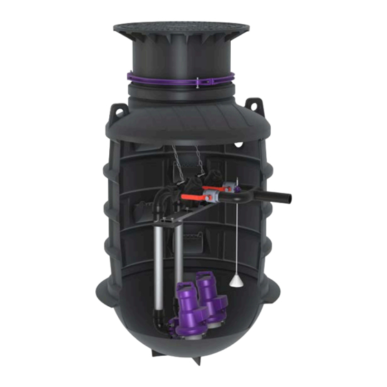
Pumping Station
Pumping Station
Aqualift XL Basic
Aqualift XL Basic
016-285_01 IL-PL
Advertisement
Chapters
Table of Contents

Subscribe to Our Youtube Channel
Related Manuals for Kessel Aqualift XL Basic


Summary of Contents for Kessel Aqualift XL Basic
- Page 1 Pumping Station Pumping Station Aqualift XL Basic Aqualift XL Basic Installation and operating manual Installation and operating manual Instructions de pose et d’utilisation..............2 Instructions de pose et d’utilisation..............2 Installation and operating instructions............17 Installation and operating instructions............17 Einbau- und Betriebsanleitung..............
-
Page 2: Table Of Contents
Maintenance................................Chère cliente, cher client, En qualité de producteur de pointe de produits novateurs dans le domaine de la technique d’assainissement, KESSEL pro- pose des réponses systématiques globales et un service orienté aux besoins de la clientèle. Nous misons simultanément sur les normes de qualité... -
Page 3: Informations Spécifiques Aux Présentes Instructions
Informations spécifiques aux présentes instructions Les conventions de représentation suivantes facilitent l’orientation : Représentation Explication voir figure 1 Numéro de repère 5 de la figure ci-contre Action de la figure Vérifier si le mode manuel a été activé. Condition de réalisation de l’action Valider <OK>. -
Page 4: Sécurité
Déterminer la classe de charge requise et la statique suivant la situation environnementale et les conditions d'uti- lisation. Demander le plan d'armature correspondant auprès de la ligne d'assistance de KESSEL. AVIS Surface contaminée ! Le système et l’environnement peuvent être souillés par des germes. - Page 5 à risques s’y rapportant et d'attirer l’attention sur ces zones, de veiller à la mise en pratique de formations se rapportant aux consignes de sécurité, d’empêcher toute personne non autorisée de l’utiliser. Personne Activités autorisées sur les postes KESSEL Exploitant Contrôle visuel, remplacement de la batterie Technicien spécialisé...
- Page 6 Les transformations ou éléments rapportés sans l’accord explicite et écrit du fabricant, l’utilisation de pièces de rechange non d’origine et les réparations effectuées par des établissements ou personnes non autorisés par le fabricant ont pour effet d'exclure tout recours à la garantie du fabricant. Description du produit Variantes Il existe plusieurs variantes du poste pour différentes profondeurs de pose.
-
Page 7: Caractéristiques Techniques
Caractéristiques techniques Cuve Matériau (cuve et refoulement) Ouverture du regard 600 mm Diamètre extérieur 1220 mm Diamètre intérieur 1000 mm Profondeurs de pose pour 1400 à 1850 mm la cuve de taille « 1300 » Profondeurs de pose pour 1900 à 2350 mm la cuve de taille «... - Page 8 1800 » 69 cm * Longueur du tuyau de refoulement mesurée à partir de la fixation jusqu’à l’extrémité inférieure de la cloche. Seul le SAV de KESSEL peut modifier la position de la cloche. Raccords de tuyaux Arrivée Surface de perçage...
-
Page 9: Montage
Montage Transport Il convient de respecter les remarques suivantes lors du transport : Le transport et le levage de la cuve ne sont autorisés qu’au moyen d'une grue (œillets de levage illustrés) ou d'un chariot élévateur (uniquement sur palette). Lors du levage, utiliser les deux anneaux de transport à proximité... - Page 10 Montage de la canalisation 4.4.1 Raccordement de la conduite de refoulement Il existe différentes options pour le raccordement de la conduite de refoulement en polyéthylène : Poser le raccord de serrage fourni (DN50) et le fixer par fermeture rotative. Par électrosoudure sur le refoulement. 4.4.2 Raccordement des tuyaux Effectuer les perçages...
- Page 11 Retirer les copeaux mais ne pas ébavurer le perçage. Répéter si besoin la procédure pour toutes les conduites souhaitées. Insérer le joint d'étanchéité pour passage de tuyau. Graisser la surface intérieure du joint. Chanfreiner l’extrémité du tuyau. Introduire le tuyau sur au moins 5 cm. Placer la(les) pompe(s) et la détection du niveau ATTENTION Les pompes, avec leurs tuyaux, sont lourdes et en...
- Page 12 Suspendre la(les) extrémité(s) de la(des) chaîne(s) sur le crochet de fixation prémonté dans la rehausse. Fixer le câble de la pompe sur la paroi de la cuve et/ou sur la rehausse avec les vis à crochet. Éviter si possible tout contact entre le câble de la pompe et les eaux usées. Faire passer le câble de la pompe dans le fourreau pour câbles à...
- Page 13 Monter/raccourcir la rehausse Insérer le joint à lèvre bien à plat. Graisser la surface intérieure du joint. Déterminer la hauteur finale du bord supérieur du terrain. Mesurer la profondeur jusqu’à laquelle la rehausse doit être insérée. Observer à cet effet la profondeur d'insertion minimale (A = 10 cm).
- Page 14 Demander le plan d'armature correspondant auprès de la ligne d'assistance de KESSEL. Envelopper le segment inférieur de béton maigre pour assurer sa fixation (voir cale de béton maigre (1)). Remblayer l’excavation avec de la pierre concassée (dia- mètre 0-16 mm), sur au moins 50 cm autour de la cuve...
-
Page 15: Mise En Service
Mise en service Pour la mise en service, observer la notice d'utilisation suc- cincte fournie. Après la mise en service/la remise, fixer le tampon avec les deux vis jointes afin de garantir la sécurité de la circu- lation (sécurité des enfants entre autres). FR : Guide de démarrage rapide Afin de garantir une performance maximale de votre station de relevage, il est nécessaire de configurer votre gestion- naire. -
Page 16: Maintenance
Maintenance Intervalle de maintenance Procéder à la maintenance selon les prescriptions de la norme en respectant au moins les intervalles suivants : Maintenance trimestrielle des postes dans les entreprises commerciales, artisanales ou industrielles Maintenance semestrielle des postes dans les maisons à plusieurs logements Maintenance annuelle des postes dans les maisons individuelles Contrôle visuel L'exploitant est tenu de contrôler l'aptitude au fonctionnement et l'étanchéité... - Page 17 Maintenance................................Dear Customer, As a premium manufacturer of innovative products for draining technology, KESSEL offers integrated system solutions and customer-oriented service. In doing so, we set the highest quality standards and focus firmly on sustainability - not only with the manufacturing of our products, but also with regard to their long-term operation and we strive to ensure that you and your property are protected over the long term.
-
Page 18: Notes On This Manual
Notes on this manual The following conventions make it easier to navigate the manual: Symbol Explanation See Figure 1 Position number 5 from the adjacent figure Action step in figure Check whether manual operation has been Prerequisite for action activated. Press OK. -
Page 19: Safety
(exception: not necessary for standard road construction). Determine the required load class and structural calculations in accordance with the environment / use condi- tions. Request an appropriate reinforcement drawing from the KESSEL hotline. NOTICE Contaminated surface! The system and surroundings can be contaminated by germs. - Page 20 Person Approved activities on KESSEL systems Operating company Visual check, inspec- tion, change of battery Technical expert, (familiar with, Emptying, cleaning...
- Page 21 Product description Variants Different versions of the system are available for different installation depths. It can be purchased as a version with one or two pumps. Control The system starts up automatically through the control unit. To this end, the control unit processes the level measurement signals.
-
Page 22: Technical Data
* The length of the pressure hose, measured from the suspension bracket to the bottom end of the submersible pressure switch. The position of the submersible pressure switch may only be changed by the KESSEL Factory Customer Service. 22 / 52... - Page 23 * The length of the pressure hose, measured from the suspension bracket to the bottom end of the submersible pressure switch. The position of the submersible pressure switch may only be changed by the KESSEL Factory Customer Service. Pipe connections...
-
Page 24: Installation
Installation Transport The following transport instructions must be followed: Transporting and lifting the tank is only allowed using a crane (illustrated lifting eyebolts) or a forklift truck (only on a pallet). When lifting, the two transport eyebolts near the upper section must be used. - Page 25 4.4.1 Connecting the pressure pipe The following options exist for connecting the pressure pipe made of polyethylene: Attach the enclosed clamp connector (DN50) and fix with a turn fastener. But sealing with heat reflectors, directly on the pressure outlet. 4.4.2 Connect the pipes Drill the holes Define the pipe routing for inlet pipe(s), cable conduit and...
- Page 26 Remove chips, but do not deburr drillhole. If necessary, repeat the above procedure until the holes for all the required pipes and cables have been made. Insert seal for pipe penetration. Grease the inside of the seal. Bevel the pipe. Insert the pipe by at least 5 cm.
- Page 27 Hang the end(s) of the chain(s) on the pre-mounted fas- tening hooks in the upper section. Use hook screws to fix the pump cable on the tank wall and/or the upper section. Where possible, avoid contact of the pump cable with water. Use the pulling wire to draw the pump cable through the cable conduit and connect as described in the enclosed control unit instructions.
- Page 28 Mount/shorten the upper section Insert the lip seal so that it is flat. Grease the inside of the seal. Determine the final height of the ground level. Measure how far the upper section must be pushed in; note the minimum insertion depth (A = 10 cm). If necessary, shorten and bevel the upper section so that the pipes are not impaired.
- Page 29 / use conditions. Request an appropriate reinforcement drawing from the KESSEL hotline. To fix the base section in place correctly, surround with lean concrete (see lean concrete wedge (1)). Fill the excavations with crushed stone (0-16 mm diam- eter), at least 50 cm all around;...
-
Page 30: Commissioning
Commissioning To put into service, follow the enclosed quick start instruc- tions. After putting into service/handover, fix the cover plate with the two enclosed screws to ensure third party safety (including child-proof lock). EN: Quick-start guide In order to ensure full performance of your pumping station it is necessary to configure your control unit. The pumping station is shipped without drilled inlet openings. -
Page 31: Maintenance
Maintenance Maintenance interval According to standard specifications, maintenance must be carried out at the following intervals: 1/4-yearly for systems in commercial operations 1/2-yearly for systems in apartment buildings yearly for systems in single-family homes Visual inspection The system must be checked once every month by the operator through observation of two switching cycles for opera- tional ability and leak-tightness. - Page 32 DoC EU Aqualift-F-XL Basic-009-214........................Liebe Kundin, lieber Kunde, als Premiumhersteller von innovativen Produkten für die Entwässerungstechnik bietet KESSEL ganzheitliche Systemlösun- gen und kundenorientierten Service. Dabei stellen wir höchste Qualitätsstandards und setzen konsequent auf Nachhaltig- keit - nicht nur bei der Herstellung unserer Produkte, sondern auch im Hinblick auf deren langfristigen Betrieb setzen wir uns dafür ein, dass Sie und Ihr Eigentum dauerhaft geschützt sind.
-
Page 33: Hinweise Zu Dieser Anleitung
Hinweise zu dieser Anleitung Folgende Darstellungskonventionen erleichtern die Orientierung: Darstellung Erläuterung siehe Abbildung 1 Positionsnummer 5 von nebenstehender Abbildung Handlungsschritt in Abbildung Prüfen, ob Handbetrieb aktiviert wurde. Handlungsvoraussetzung OK betätigen. Handlungsschritt Anlage ist betriebsbereit. Handlungsergebnis Querverweis auf Kapitel 2 siehe "Sicherheit" Fettdruck besonders wichtige oder sicherheitsrelevante Information Variante oder Zusatzinformation (z. -
Page 34: Sicherheit
Statik für Verkehrssicherheit beachten. Schachtverbau für Lastklasse D erfordert eine Lastverteilplatte aus armier- tem Beton (Ausnahme: bei Standardstraßenaufbau nicht erforderlich). Erforderliche Lastklasse und Statik gemäß Umgebung/Nutzungsbedingungen ermitteln. Entsprechenden Bewehrungsplan bei KESSEL-Hotline anfordern. ACHTUNG Kontaminierte Oberfläche! Anlage und Umgebung können durch Keime verunreinigt sein. - Page 35 Der Betreiber der Anlage ist dazu verpflichtet: eine Gefährdungsbeurteilung zu erstellen, entsprechende Gefährdungszonen zu ermitteln und auszuweisen, Sicherheitsunterweisungen durchzuführen, gegen die Benutzung durch Unbefugte zu sichern. Person freigegebene Tätigkeiten an KESSEL-Anlagen Betreiber Sichtprüfung, Batterietausch Sachkundiger (kennt, ver- Entleerung, Reinigung steht Betriebsanweisung)
- Page 36 Steuerung Die Anlage läuft durch die Steuerung im Schaltgerät selbsttätig an. Hierzu verarbeitet das Schaltgerät die Signale der Niveauerfassung. Diese Anlage setzt als Niveauerfassung standardmäßig einen Druckschlauch ein. Ist der definierte Füllstand erreicht, wird das Abpumpen aktiviert. Nachdem der Füllstand wieder entsprechend abgesunken ist, wird das Abpumpen beendet. Sind zwei Pumpen angeschlossen, werden diese, je nach Füllstand und Positionierung der Niveauerfassung, entweder ein- zeln oder gemeinsam eingeschaltet.
-
Page 37: Technische Daten
Behältergröße "1300" 33 cm * Die Länge des Druckschlauches gemessen von der Aufhängung bis zum unteren Ende der Tauchglocke. Die Position der Tauchglocke darf nur durch den KESSEL-Werkskundendienst verändert werden. 016-285_01 IL-PL Installation and operating manual 37 / 52... - Page 38 Länge Druckschlauch* bei Behältergröße "1800" 69 cm * Die Länge des Druckschlauches gemessen von der Aufhängung bis zum unteren Ende der Tauchglocke. Die Position der Tauchglocke darf nur durch den KESSEL-Werkskundendienst verändert werden. Rohranschlüsse Zulauf Anbohrfläche Anschluss Druckleitung [DN] Kabelleerrohr Anbohrfläche...
-
Page 39: Montage
Montage Transport Folgende Hinweise zum Transport sind zu beachten: Der Transport und das Anheben des Behälters ist nur mittels Kran (abgebildete Hebeösen) oder mittels Gabel- stapler (nur auf Palette) erlaubt. Beim Anheben sind die beiden Transportösen in der Nähe des Aufsatzstückes zu verwenden. An den Transportösen darf der Behälter nur mit Hanfsei- len oder Gewebegurten angehoben werden, Drahtseile oder Ketten sind nicht zulässig. - Page 40 Rohrleitungen montieren 4.4.1 Druckleitung anschließen Für das Anschließen der Druckleitung aus Polyethylen bestehen folgende Optionen: Den beiliegenden Klemmverbinder (DN50) aufsetzen und per Drehverschluss fixieren. Das Spiegelschweißen direkt auf den Druckausgang. 4.4.2 Rohre anschließen Bohrungen durchführen Rohrführung für Zulaufleitung(en), Kabelleerrohr und Ent- lüftungsleitung definieren.
- Page 41 Späne entfernen, Bohrung aber nicht entgraten. ggf. Vorgehensweise wiederholen bis alle gewünschten Leitungen ausgeführt sind. Dichtung zur Rohrdurchführung einsetzen. Dichtung innen einfetten. Rohrende anphasen. Rohr mind. 5 cm einführen. Pumpe(n) und Niveauerfassung einsetzen VORSICHT Pumpen mit Verrohrungen sind schwer und teil- weise unhandlich.
- Page 42 Ende(n) der Kette(n) an den vormontierten Befestigungs- haken im Aufsatzstück einhängen. Pumpenkabel mit Hakenschrauben an Behälterwand und/ oder am Aufsatzstück fixieren. Der Kontakt des Pumpen- kabels mit Abwasser sollte nach Möglichkeit vermieden werden. Pumpenkabel mit dem Durchzugsdraht durch das Kabel- leerohr verlegen und gemäß...
- Page 43 Aufsatzstück montieren/kürzen Lippendichtung plan einsetzen. Dichtung innen einfetten. Finale Höhe der Geländeoberkante bestimmten. Ausmessen, wie weit das Aufsatztück eingeschoben wer- den muss, dabei Mindesteinstecktiefe (A = 10 cm) beach- ten. Falls erforderlich, Aufsatzstück kürzen und anphasen, sodass Rohre nicht beeinträchtigt werden. Aufsatzstück einsetzen und mit Klemmring fixieren.
- Page 44 Beton (Ausnahme: bei Standardstra- ßenaufbau nicht erforderlich). Erforderliche Lastklasse und Statik gemäß Umgebung/Nutzungsbedingungen ermitteln. Entsprechenden Bewehrungsplan bei KESSEL- Hotline anfordern. Zur sauberen Fixierung Bodenteil ggf. mit Magerbeton umfüllen (siehe Magerbetonkeil (1)). Grube mit Bruchschotter (0-16 mm Durchmesser), mind.
-
Page 45: Inbetriebnahme
Inbetriebnahme Zur Inbetriebnahme die beiliegende Kurzbedienungsanlei- tung beachten. Nach der Inbetriebnahme/Übergabe die Abdeckplatte mit den beiden beiliegenden Schrauben fixieren um die Ver- kehrssicherungspflicht (u. a. Kindersicherung) zu gewähr- leisten. DE: Kurzbedienungsanleitung Damit die volle Leistungsfähigkeit der Pumpstation gewährleistet ist muss das der Anlage zugehörige Schaltgerät einge- stellt werden. -
Page 46: Wartung
Wartung Wartungsintervall Die Wartung muss gemäß Normvorgabe in folgenden Zeitabständen erfolgen: 1/4-jährlich bei Anlagen in Gewerbebetrieben 1/2-jährlich bei Anlagen für Mehrfamilienhäuser jährlich bei Anlagen für Einfamilienhäusern Sichtkontrolle Die Anlage ist monatlich vom Betreiber durch Beobachtung von zwei Schaltspielen auf Betriebsfähigkeit und Dichtheit zu überprüfen. - Page 51 016-285_01 IL-PL 51 / 52...
- Page 52 Registrieren Sie Ihr Produkt online, um von einer schnelleren Hilfe zu profitieren! http://www.kessel.de/service/produktregistrierung.html KESSEL AG, Bahnhofstr. 31, 85101 Lenting, Deutschland...
Need help?
Do you have a question about the Aqualift XL Basic and is the answer not in the manual?
Questions and answers