Table of Contents
Advertisement
Quick Links
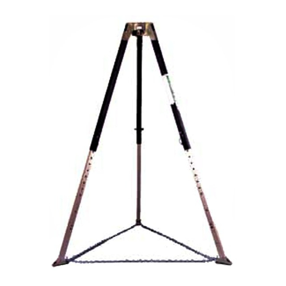
LYNX TRIPOD ™
FALL-RESCUE™ WORK SYSTEM
National standards and state, provincial and federal laws require the user to be
trained before using this product. Use this manual as part of a user safety training
program that is appropriate for the user's occupation. These instructions must
be provided to users before use of the product and retained for ready reference
by the user. The user must read, understand (or have explained), and heed all
instructions, labels, markings and warnings supplied with this product and with
those products intended for use in association with it. FAILURE TO DO SO MAY
RESULT IN SERIOUS INJURY OR DEATH.
1.0
TRIPOD MODELS AND SPECIFICATIONS
TABLE 1. LYNX TRIPOD MODELS COVERED BY THESE INSTRUCTIONS
Working
Height
Model No.
IN
10022050
91
2.3
120 3.0
10022051
1.1
SPECIFICATIONS - LYNX TRIPOD
•
All Lynx Tripod Fall-Rescue Work Systems meet ANSI Z359.1 and applicable OSHA regulations when
leg base chain is installed and properly adjusted.
•
The Lynx Tripod head is zinc plated alloy steel, the Lynx Tripod legs are anodized, high-tensile, aluminum
alloy.
•
Capacity for personnel is 310 lbs (140 kg) including weight of the user plus clothing, tools and other
user-borne objects.
•
Capacity for material is 620 lbs (280 kg).
TWP 705 (L) Rev. 2
User Instructions
Weight
Skid Resistant
LBS
KG
M
43
19.5
49
22.2
© MSA 2006
Model No.
Serial No.
!
WARNING
Leg Base
Feet
Chain
YES
YES
YES
YES
Prnt. Spec. 10000005389 (R)
Carrying
Anchorage
Strap
Pins
OPTIONAL
YES
OPTIONAL
YES
Mat. 10022053
Doc. 10022053
Advertisement
Table of Contents

Related Manuals for MSA FALL-RESCUE 10022050


Summary of Contents for MSA FALL-RESCUE 10022050
- Page 1 Capacity for personnel is 310 lbs (140 kg) including weight of the user plus clothing, tools and other user-borne objects. • Capacity for material is 620 lbs (280 kg). TWP 705 (L) Rev. 2 © MSA 2006 Prnt. Spec. 10000005389 (R) Mat. 10022053 Doc. 10022053...
- Page 2 91 in (2.3 m) 115 in (2.9 m), Legs at minimum extension: 55 in (1.4 m) 79 in (2.0 m). Notes:Adding equipment at Lynx Tripod head reduces headroom. See Figure 1 for dimension references. FIGURE 1: P/N 10022053 Copyright © 2002, MSA...
- Page 3 1910.146 and ANSI Z117.1. Training must be conducted without undue exposure of the trainee to hazards. The effectiveness of training should be periodically assessed (at least annually) and the need for more training or retraining determined. MSA offers training programs. Contact MSA for training information. DESCRIPTION OF LYNX TRIPOD The Lynx Tripod is an anchorage connector intended for both personnel- and material-moving applications.
- Page 4 MSA P/N 506473. 3.1.4.2 The MSA wire rope model Dyna-Locks and Lynx Rescuers attach to the Lynx Tripod by means of leg mounting brackets. The Model 506216 Dyna-Lock/Lynx Rescuer mounting bracket adapts 22 m and 30 m units to the Lynx Tripod;...
- Page 5 LYNX TRIPOD OPTIONAL ACCESSORIES Refer to the individual User Instructions for each of the optional accessories for information regarding integration with the Lynx Tripod or other system components. Contact MSA for information on these optional accessories and their use in integrated systems.
- Page 6 MSA DYNESCAPE™ DESCENT CONTROL DEVICES: Model 506416, Manual Descender; or Model 506262, Automatic Descender. See separate instructions P/N 621883 or 622081, respectively. 3.3.8 MSA FALLBLOC™ FALL ARREST/EMERGENCY DESCENT SYSTEM: Model 501500. See separate instructions P/N 621210. 3.3.9 MSA CARABINERS: Models 506298, 506308, 506572. See separate instructions P/N 622543.
-
Page 7: Typical Applications
Consult a physician if there is any question about physical ability to safely use this product to arrest a fall or suspend. WARNING Do not alter this equipment or intentionally misuse it. Copyright © 2002, MSA P/N 10022053... -
Page 8: System Requirements
HAZARDS: • Acidic, alkaline, or other environments with harsh substances may damage the hardware elements of this Lynx Tripod. If working in a chemically aggressive environment, consult MSA to determine acceptable system components for your specifi c conditions. • Do not use Lynx Tripod in environments with temperatures greater than 185° F (85° C). -
Page 9: Planning The Use Of Systems
Lynx Tripod anchorage connectors are designed to be used with MSA approved components and connecting subsystems. Use of the Lynx Tripod with products made by others that are not approved in writing by MSA may adversely affect the functional compatibility between system parts and the safety and reliability of the complete system. - Page 10 Lynx Tripod head. Refer to the User Instructions supplied with each system component to determine the effect on overhead clearance due to such installation. P/N 10022053 Copyright © 2002, MSA...
- Page 11 Consult the manufacturer’s instructions for the particular connecting subsystem or component for clearance needed. Copyright © 2002, MSA P/N 10022053...
- Page 12 You will note that each leg feet-down position. automatically snaps upwardly when the hinge locks. Check to be certain of hinge locking. CAUTION Potential pinch point. DO NOT touch tripod leg within six (6) inches of the tripod head. P/N 10022053 Copyright © 2002, MSA...
- Page 13 The Lynx Tripod head should be horizontal when installation is complete. Be careful not to extend each leg too far in each increment so as to cause the Lynx Tripod to topple. Copyright © 2002, MSA P/N 10022053...
- Page 14 USE OF ATTACHMENT PINS: The Positive Locking Pin is used to mount the optional MSA Split-Mount Pulley P/N 506222, and may also be used to connect directly with a MSA Carabiner. The Split-Mount Pulley is designed to work in conjunction with a Lynx Rescuer, where the cable of the Lynx Rescuer would pass through the Side-Mount Pulley and descend into the center of the work access.
- Page 15 LYNX TRIPOD Page 15 components, such as the MSA Fallbloc Lifeline. The Hitch Pin is used to mount the optional Lynx Boom Hoist. See section 7.5. Contact MSA for information about connection of optional components to the Lynx Tripod or refer to the separate User Instructions provided with each component.
- Page 16 Pin in place with the ball lock pin (F). Step 4: Complete installation of the tripod in accordance with the instructions accompanying the product. P/N 10022053 Copyright © 2002, MSA...
-
Page 17: Care Maintenance And Storage
Most of these systems require special engineering design, testing, controlled installation and su- pervised training and use in order to be safe. MSA has developed a system offered as part of its product line which does not require special engineering to be put into use. This is the FRWS (Fall-Rescue Work System) utilizing the Lynx Tripod (portable tripod). -
Page 18: Labels And Markings
Grid must be punched with a date (month/year) within the last six months. If not, remove the Lynx Tripod from use and mark it as “UNUSABLE” until a Formal Inspection is performed in accordance with section 12. See section 4 for location of labels. P/N 10022053 Copyright © 2002, MSA... - Page 19 USER INSTRUCTIONS LYNX TRIPOD Page 19 Part Number/N° de Piéce Date of Mfr./Date de Manuf. Serial Number/ N° de Série Copyright © 2002, MSA P/N 10022053...
-
Page 20: Inspection Before Each Use
“UNUSABLE” until repaired. For fi nal disposition, submit the Lynx Tripod to a competent person who is authorized to perform Formal Inspection. If there is any question as to repairability, contact MSA or a service center authorized in writing by MSA before further use of the Lynx Tripod. - Page 21 LYNX TRIPOD Page 21 10.0 FORMAL INSPECTION CAUTION Only MSA or parties with written authorization from MSA may make repairs to the Lynx Tripod. 10.1 FORMAL INSPECTION PROCEDURAL STEPS Step 1: Record on the LOG the Model No., Serial No. and Date Made information shown on this user instruction and from the product labels.
- Page 22 Non-Metallic Burns/heat exposure Chemical exposure NN - (Non-Metallic not acceptable) Cracked/Split (2) If there are three or more Overall As- sessment Codes of “N” type on a Priority 2 Other item. No visible change P/N 10022053 Copyright © 2002, MSA...
- Page 23 Hitch Pin Positive Locking Pin LYNX TRIPOD LEGS Clevis Pin with Attached Ring Upper Leg Lower Leg Positive Locking Pin Chain Connector Foot Leg Base Chain Screw Lock Link NON-METALLIC PARTS Labels Skid-Resistant Pad Copyright © 2002, MSA P/N 10022053...
- Page 24 fi rst. MSA shall be released from all obligations under this warranty in the event repairs or modifi cations are made by persons other than its own authorized service personnel or if the warranty claim results from misuse of the product.
Need help?
Do you have a question about the FALL-RESCUE 10022050 and is the answer not in the manual?
Questions and answers