Moxa Technologies EtherDevice EDS-P206A-4PoE Series Quick Installation Manual
Hide thumbs
Also See for EtherDevice EDS-P206A-4PoE Series:
- Hardware installation manual (16 pages) ,
- Hardware installation manual (15 pages)
Table of Contents
Advertisement
Quick Links
EDS-P206A-4PoE Series
Quick Installation Guide
Moxa Americas:
Toll-free: 1-888-669-2872
Tel:
1-714-528-6777
Fax:
1-714-528-6778
Moxa Europe:
Tel:
+49-89-3 70 03 99-0
Fax:
+49-89-3 70 03 99-99
Moxa India:
Tel:
+91-80-4172-9088
Fax:
+91-80-4132-1045
Moxa EtherDevice
Edition 4.0, January 2017
Technical Support Contact Information
www.moxa.com/support
2017 Moxa Inc. All rights reserved.
TM
Switch
Moxa China (Shanghai office):
Toll-free: 800-820-5036
Tel:
+86-21-5258-9955
Fax:
+86-21-5258-5505
Moxa Asia-Pacific:
Tel:
+886-2-8919-1230
Fax:
+886-2-8919-1231
P/N: 1802002060013
*1802002060013*
Advertisement
Table of Contents

Subscribe to Our Youtube Channel
Related Manuals for Moxa Technologies EtherDevice EDS-P206A-4PoE Series


Summary of Contents for Moxa Technologies EtherDevice EDS-P206A-4PoE Series
- Page 1 EDS-P206A-4PoE Series Quick Installation Guide Moxa EtherDevice Switch Edition 4.0, January 2017 Technical Support Contact Information www.moxa.com/support Moxa Americas: Moxa China (Shanghai office): Toll-free: 1-888-669-2872 Toll-free: 800-820-5036 Tel: 1-714-528-6777 Tel: +86-21-5258-9955 Fax: 1-714-528-6778 Fax: +86-21-5258-5505 Moxa Europe: Moxa Asia-Pacific: Tel: +49-89-3 70 03 99-0 Tel: +886-2-8919-1230...
-
Page 2: Package Checklist
Overview The EDS-P206A-4PoE series industrial Ethernet switches are entry-level industrial 6-port PoE Ethernet switches that support IEEE 802.3, IEEE 802.3u, and IEEE 802.3x, with 10/100M, full/half-duplex, MDI/MDIX auto-sensing, IEEE 802.3af, and IEEE 802.3at. The EDS-P206A-4PoE series provides 12/24/48 VDC redundant power inputs that can be connected simultaneously to a live DC power source. - Page 3 EDS-P206A-4PoE (Standard) Panel Layouts 1. Grounding screw 2. Terminal block for power input P1/P2 3. DIP switches 4. Power input P1 LED 5. Power input P2 LED 6. PoE LED 7. 10/100BaseT(X) port 8. TP port’s 10/100 Mbps LED 9. Model name 10.
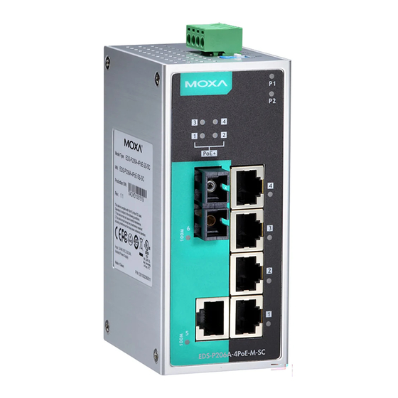
- Page 4 EDS-P206A-4PoE-M-SC/ST Panel Layouts NOTE: The EDS-P206A-4PoE-S-SC/ST are identical in appearance to the EDS-P206A-4PoE-M-SC/ST. 1. Grounding screw 2. Terminal block for power input P1/P2 3. DIP switches 4. Power input P1 LED 5. Power input P2 LED 6. PoE LED 7. 10/100BaseT(X) port 8.
- Page 5 EDS-P206A-4PoE-MM-SC/ST Panel Layouts NOTE: The EDS-P206A 4PoE-SS-SC/ST are identical in appearance to the EDS-P206A-4PoE- MM-SC/ST. 1. Grounding screw 2. Terminal block for power input P1/P2 3. DIP Switches 4. Power input P1 LED 5. Power input P2 LED 6. PoE LED 7.
-
Page 6: Mounting Dimensions
Mounting Dimensions Unit = mm (inch) DIN-Rail Mounting The aluminum DIN-Rail attachment plate should already be fixed to the back panel of the EDS when you take it out of the box. If you need to reattach the DIN-Rail attachment plate, make sure the stiff metal spring is situated towards the top, as shown in the figures below. -
Page 7: Wall Mounting (Optional)
Wall Mounting (optional) For some applications, you will find it convenient to mount the EDS-P206A-4PoE on the wall, as shown in the following figures. STEP 1: Remove the aluminum DIN-Rail attachment plate from the EDS-P206A-4PoE’s rear panel, and then attach the wall mount plates as shown in the diagram at the right. -
Page 8: Grounding The Etherdevice Switch
WARNING Safety First! Calculate the maximum possible current in each power wire and common wire. Observe all electrical codes dictating the maximum current allowable for each wire size. If the current goes above the maximum ratings, the wiring could overheat, causing serious damage to your equipment. -
Page 9: Communication Connections
ATTENTION Before connecting the EtherDevice Switch to the DC power inputs, make sure the DC power source voltage is stable. Communication Connections The EDS-P206A-4PoE switches have 4, 5, or 6 10/100BaseT(X) Ethernet ports, and 2, 1, or 0 (zero) 100BaseFX multi/single-mode (SC/ST-type connector) fiber ports. - Page 10 RJ45 (8-pin) to RJ45 (8-pin) Straight-Through Cable Wiring RJ45 (8-pin) to RJ45 (8-pin) Cross-Over Cable Wiring NOTE If the PD only supports MDI mode (V+, V+, V-, V- for pins 1, 2, 3, 6), choose a cross-over Ethernet cable to connect the PD and the EDS switch.
-
Page 11: Redundant Power Inputs
ST-Port Pinouts ST-Port to ST-Port Cable Wiring ATTENTION This is a Class 1 Laser/LED product. To avoid causing serious damage to your eyes, do not stare directly into the Laser Beam. Redundant Power Inputs Both power inputs can be connected simultaneously to live DC power sources. -
Page 12: Led Indicators
LED Indicators The front panel of the EDS switches contains several LED indicators. The function of each LED is described in the following table. Color State Description Power is being supplied to power input AMBER Power is not being supplied to power input P1. -
Page 13: Dual Speed Functionality And Switching
Dual Speed Functionality and Switching The Moxa EtherDevice Switch’s 10/100 Mbps switched RJ45 port auto negotiates with the connected device for the fastest data transmission rate supported by both devices. All models of Moxa EtherDevice Switch are plug-and-play devices, so that software configuration is not required at installation, or during maintenance. -
Page 14: Auto-Negotiation And Speed Sensing
Auto-Negotiation and Speed Sensing All of the EDS’s RJ45 Ethernet ports independently support auto-negotiation for speeds in the 10BaseT and 100BaseTX modes, with operation according to the IEEE 802.3u standard. This means that some nodes could be operating at 10 Mbps, while at the same time, other nodes are operating at 100 Mbps. - Page 15 Optical Fiber 100BaseFX Multi-mode Single-mode 50/125 μm Fiber Cable Type G.652 800 MHz*km Typical Distance 4 km 5 km 40 km Typical (nm) 1300 1310 Wavelength TX Range (nm) 1260 to 1360 1280 to 1340 RX Range (nm) 1100 to 1600 1100 to 1600 TX Range (dBm) -10 to -20...
- Page 16 Physical Characteristics Housing Metal, IP30 protection Dimensions 50 x 114 x 70 mm Weight 275 g Installation DIN-Rail Mounting, Wall Mounting (with optional kit) Environmental Limits Operating Temperature Standard models: -10 to 60°C (32 to 140°F) Wide temp. models: -40 to 75°C (-40 to 167°F) Storage Temperature -40 to 85°C (-40 to 185°F) Ambient Relative...
Need help?
Do you have a question about the EtherDevice EDS-P206A-4PoE Series and is the answer not in the manual?
Questions and answers